Catalog excerpts
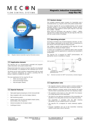
OPERATING INSTRUCTIONS MENKAR Level indicator © MECON GmbH BA / MENKAR / EN / 19-10
Open the catalog to page 1
© MECON GmbH BA / MENKAR / EN /
Open the catalog to page 2
IMPRINT All rights reserved. Any reproduction or usage without the written authorisation of MECON GmbH - even partial content - is strictly prohibited. Subject to change without notice. Copyright 2019 MECON GmbH - Röntgenstr. 105 - 50169 Kerpen - Germany © MECON GmbH BA / MENKAR / EN / 19-10
Open the catalog to page 3
SAFETY INSTRUCTIONS 1 SAFETY INSTRUCTIONS 1.1 Intended use MENKAR series level indicators are suitable for continuous measurement and monitoring of the level of a liquid in open or closed containers as required. The liquid level in the container to be monitored is transmitted by a float in a 1:1 ratio as an analogue value. The measurement is independent of the operating pressure. The instruments are noted for their robust construction, trouble-free usage and good readability, even from further away. Various magnetically operated contact units for control and regulation processes (acoustic...
Open the catalog to page 4
SAFETY INSTRUCTIONS 1.2 Certifications CE marking 0035 By affixing the CE mark, the manufacturer certifies that the MENKAR level indicator, where applicable, complies with the legal requirements of the following EU directive: »» Pressure Equipment Directive 2014/68/EU »» The permitted media are Group 1 gases and liquids »» Class III (Classification under the condition PS.V <1000 (Article 4.1.1a) 1.3 Manufacturer’s safety instructions Disclaimer The manufacturer is not liable for damages of any kind caused by the use of the instrument, including, but not limited to, direct, indirect,...
Open the catalog to page 5
INSTRUMENT DESCRIPTION 2 INSTRUMENT DESCRIPTION 2.1 Scope of delivery MENKAR with local indicator, cap and drain plug Float Valve (vent/drain) - optional Operating instructions Optional: Magnetic flapper (mounted), contacts, reed chain © MECON GmbH BA / MENKAR / EN / 19-10
Open the catalog to page 6
INSTRUMENT DESCRIPTION Type Drawing No. Serial No. Connection C to C Ts min. / max. p min. / max. p max. at Ts max. Material Specific density CE TAG No. Device name Drawing number Serial number Process connection Nozzle distance (centre to centre) Temperature range (min./max.) of medium in °C Pressure (min / max) Maximum permissible operating pressure at Ts max. Material used for the wetted parts Relative density C E marking, classification according to the Pressure Equipment Directive TAG number © MECON GmbH BA / MENKAR / EN / 19-10
Open the catalog to page 7
INSTALLATION AND PRINCIPLE OF OPERATION 3 INSTALLATION AND PRINCIPLE OF OPERATION 3.1 Installation notes Information! All instruments are carefully checked for proper functionality before shipment. Immediately on receipt, check the outer packing carefully for damage or signs of improper handling. Report any damage to the carrier and your local sales staff. In such cases, a description of the damage, the type and the serial number of the instrument should be given. Unpack the instrument carefully to avoid damage. Check the delivery for completeness on the basis of the delivery note and the...
Open the catalog to page 8
INSTALLATION AND PRINCIPLE OF OPERATION The following points should be noted when installing the instruments in the pipeline: »» Remove the transport lock from the valve. »» Before installation, check that the float in the valve can move freely without jamming. 3.3 Installation instructions »» The effective pressure of the installation (the maximum pressure allowed by the pres- sure relief valve) must never exceed the maximum allowable pressure PS indicated on the nameplate. »» The user must ensure that the materials (guide tube, floats, seals, etc.) that come into contact with the fluid...
Open the catalog to page 9
INSTALLATION AND PRINCIPLE OF OPERATION 3.5 Display of the actual level The float is equipped with a ring system made of permanent magnets in order to transmit the liquid level. For design reasons, the minimum level in the measuring tube is indicated by the axis of the lower lateral connecting flange, i.e. the zero point forms the centre line of the lower connecting flange. In the event of a major change in the product density specified in the order, or when installing another float, the scale on the MENKAR may need to be adjusted to ensure a correct reading. In such a case, please contact...
Open the catalog to page 10
3.8 Configuration MENKAR level indicators are manufactured in lengths of up to 5,000 mm, depending on the type, and with a split design for longer lengths in order to facilitate transport. The connection is made using flanges. The following points must be observed taking account of the particular operating data and local conditions: »» Type of fitting »» Type and design of instrument »» Length / measuring range »» Scale type (%, volume or height units): For scales in volume units, the user must provide an outflow table. The scale can also be retrofitted and installed by the user. For...
Open the catalog to page 11
We reserve the right to change technical data as a result of technological progress. The latest information on this product can be found at www.mecon. You can also contact our sales department via e-mail at info@mecon.de. 5 TECHNICAL DATA 5.1 Max. pressure 16 bar, 150 lbs © MECON GmbH BA / MENKAR / EN / 19-10
Open the catalog to page 12
TECHNICAL DATA Stainless steel 1.4404 (316L), stainless steel 1.4301 (304), PP, PVC, PVDF, PE, Monel, Titanium, Hastelloy, 6Mo Measuring length Up to 5500 mm in 1 piece, longer in several parts Indicator rail Polycarbonate (max temp. +105 °C, temporary +120 °C) Process connection DIN DN 15 – DN 32 / PN 16, B = 75 mm ANSI ½” – 1¼” 150# RF (RTJ), B = 85 mm Welding end / thread (external / internal thread), W = 70 mm DN 40 – DN 50 and ANSI 1.½” – 2” on 1” pipe, B = 130 mm ¼ ", ½" or ¾ "plug or valve BSP / NPT or flange Side entry as above Additional flange according to DIN or ANSI Without...
Open the catalog to page 13All MECON catalogs and technical brochures
-
 MENKAR
28 Pages
-
 Turbo-Lux® 3
20 Pages
-
 N4
N420 Pages
-
 Gardex
5 Pages
-
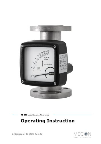 RE 250
32 Pages
-
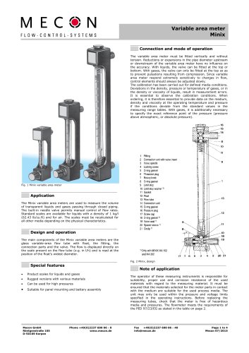 Minix
Minix4 Pages
-
 Tubux M30
20 Pages
-
 KBF
KBF20 Pages
-
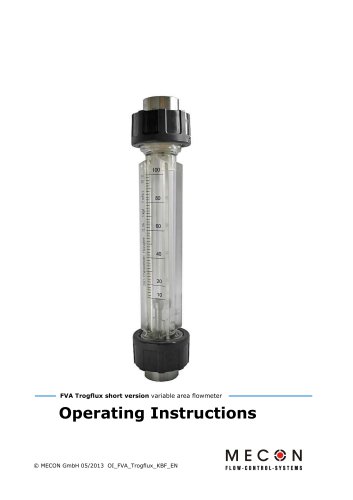
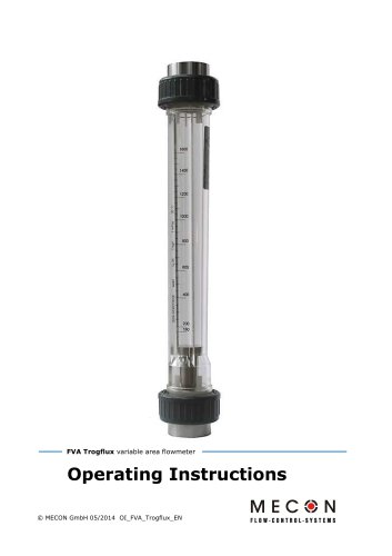 Trogflux
21 Pages
-
 mag-flux M1
35 Pages
-
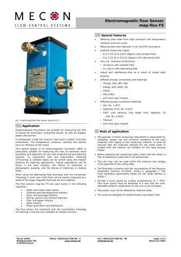 mag-flux F5
4 Pages
-
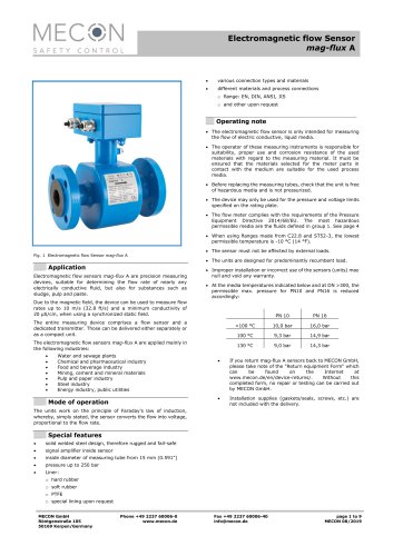 mag-flux A
9 Pages
-
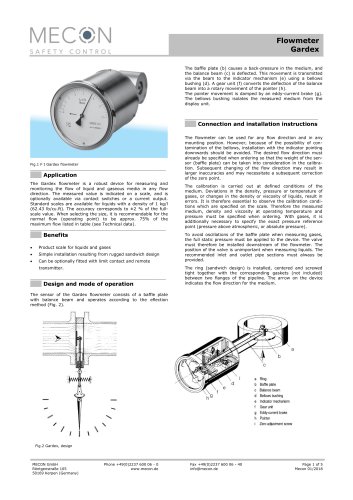
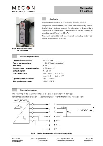 Flowmeter F I Gardex
1 Pages
-
 Product catalogue
24 Pages