MCC 172
1 /5Pages

MCC 172
1 /5Pages
Catalog excerpts

MCC 172 IEPE Measurement DAQ HAT for Raspberry Pi® Features • Two IEPE inputs − Two 24-bit, 51.2 kS/s A/D converters (one per channel) − AC coupled at ±5 V − 10-32 and screw terminal connections for OEM support • Synchronous ADC conversions between multiple boards The MCC 172 is a 24-bit DAQ HAT for making sound and vibration measurements from IEPE sensors. The MCC 172 is shown connected to a Raspberry Pi (not included). Overview The MCC 172 is a voltage HAT (Hardware Attached on Top) board designed for use with Raspberry Pi, the most popular single-board computer on the market today. A HAT is an add-on board with a 40W GPIO (general purpose input/output) connector that conforms to the Raspberry Pi HAT specification. The MCC 172 HAT provides two analog inputs for sound or vibration measurements. Up to eight MCC HATs can be stacked onto one Raspberry Pi. • Onboard sample buffers allow high-speed acquisition • External digital trigger input • Stack up to eight MCC HATs onto a single Raspberry Pi Software • MCC DAQ HAT Library; available on GitHub Supported Operating Systems • Linux®/Raspbian The MCC 172 header plugs into the 40-pin general purpose I/O (GPIO) connector on a user-supplied Raspberry Pi. The MCC 172 was tested for use with all Raspberry Pi models with the 40-pin GPIO connector. Multiple MCC 172 HATs can be synchronized to a single sampling clock. The clock is programmable for sampling rates between 51.2 kS/s to 200 S/s. • Single-board: max throughput is 102.4 kS/s (51.2 kS × 2 channels) HAT configuration parameters are stored in an on-board EEPROM that allows the Raspberry Pi to automatically set up the GPIO pins when the HAT is connected. Sample Rates • Stacked boards: max throughput is 307.2 kS/s aggregate1. Digital Trigger Stackable HATs Up to eight MCC HAT boards can be stacked onto a single Raspberry Pi. Users can mix and match MCC HAT models in the stack. Analog Input The two 24-bit differential analog input channels simultaneously acquire data at rates up 51.2 kS/s. Users can turn IEPE excitation current on or off. Each channel has a dedicated A/D converter. Both ADCs share the same clock and are synchronized to start conversions at the same time for synchronous data. The trigger input (terminal TRIG) is used to delay an input scan until a specified condition is met at the trigger input. The trigger input signal may be a 3.3V or 5V TTL or CMOS logic signal. The input condition may be edge or level sensitive, rising or falling edge, or high or low level. This terminal may be used to trigger the start of an acquisition on multiple synchronized MCC 172 HATs. OEM Support Users can connect analog input signals to either the 10-32 coaxial inputs or to the screw terminals. Only one source may be connected to a channel at a time. MCC DAQ HAT Library The open-source MCC DAQ HAT Library of commands in C/C++ and Python allows users to develop applications on the Raspberry Pi using Linux. The library is available to download from GitHub. Comprehensive API and hardware documentation is available. The MCC DAQ HAT Library supports operation with multiple MCC DAQ HATs running concurrently. Console-based and user interface (UI) example programs are available for each API. The MCC 172 is powered with 5 V provided by the Raspberry Pi through the GPIO header connector. 1 Dependent on the load on the Raspberry Pi and the SPI interface. Measurement Computing
Open the catalog to page 1
IEPE Supply Clock Master/ Slave IEPE Supply Board Address Matching ADC HAT EEPROM Trigger Master/ Slave Digital Trigger Stackable Connect up to eight MCC DAQ HATs onto a single Raspberry Pi. Onboard jumpers identify each board in the stack. Measurement Computing
Open the catalog to page 2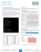
MCC 172 Example Programs MCC DAQ HAT Examples User Interface The MCC DAQ HAT Library includes example programs developed in C/C++ and Python that users can run to become familiar with the DAQ HAT library and boards; source code is included. Example programs featuring a user interface are provided in different formats. Examples of each are shown here. Console-Based (C/C++ and Python) The data logger example shows how to acquire data from the MCC 172, display the data on a strip chart, and log the data to a CSV file. This example can be run from the terminal. Data Logger (C/C++) Console-based examples...
Open the catalog to page 3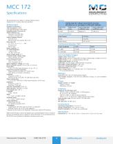
All specifications are subject to change without notice. Typical for 25 ˚C unless otherwise specified. Analog input AC voltage measurement accuracy (all values are (±) and apply to calibrated readings) Analog input Number of channels: 2 ADC Resolution: 24 bits A/D converter type: Delta sigma Sampling mode: Simultaneous Master timebase (fM): Frequency: 26.2144 MHz Accuracy: ±50 ppm max Master timebase sources Internal clock Shared clock from another MCC 172 Data rates (fS) (fM / 512) / n, n = 1, 2, …, 256 51.2 kS/s max 200 S/s min Input coupling: AC AC cutoff frequency -3 dB: 0.78 Hz -0.1 dB:...
Open the catalog to page 4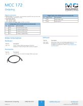
MCC 172 Ordering Signal connectors Trigger input screw terminal pinout (Connector J5) Connector types: 10-32 coaxial / screw terminal (in parallel; only one source may be connected to a channel at a time) Coaxial input signals CH0: channel 0 input CH1: channel 1 input Screw terminal wire gauge range: 16 AWG to 30 AWG Signal name Digital trigger input Digital ground Analog input screw terminal pinout (Connector J2) Pin Signal name Channel 0 positive input Channel 0 negative input Channel 1 positive input Channel 1 negative input Order Information 24-bit, 2-channel IEPE measurement DAQ HAT. Raspberry...
Open the catalog to page 5All Measurement Computing catalogs and technical brochures
 ECONseries
10 Pages
 USB Digital I/O
7 Pages
 USB-3100 Series
7 Pages
 DT9853 & DT9854
4 Pages
 USB-5200 Series
6 Pages
 USB-1608G Series
6 Pages
 USB-200 Series
5 Pages
 Data-Acquisition-Catalog
8 Pages
 USB-5100 series
8 Pages
 USB-500/600 series
11 Pages
 USB-1608FS-Plus
5 Pages
 WebDAQ 316
7 Pages


- Liebherr monitoring analyzer
- Data logger
- Digital I/O
- IO module
- Liebherr benchtop analyzer
- Temperature datalogger
- Analog I/O
- Digital IO module
- Liebherr portable analyzer
- Liebherr laboratory analyzer
- Wireless datalogger
- Digital analyzer
- Liebherr compact analyzer
- Power quality analyzer
- Liebherr sampling analyzer
- Data acquisition unit
- Spectrum analyzer
- Multi-channel datalogger
- Liebherr simultaneous analyzer
- Power analyzer