- Catalogs
- Meagacon AS
- K P M 1 6 x
K P M 1 6 x
1 /5Pages

K P M 1 6 x
1 /5Pages
Catalog excerpts

INSULATION GUARD FOR NON-GROUNDED AC NETWORKS KPM16x • Direct connection up to 500V line voltage, up to 25kV with HV adapter • Monitoring during both live and standby conditions • For use in land, marine, offshore, sub-sea and ocean floor Installations • Comply with AODC 035 Code of Practice • ”Megger” - safe to 1.4kVDC when aux power is OFF • Immune to earth capacitance and voltage surges • Analogue output proportional to meter reading (F-version) Specifications General Auxiliary Supply: Optional Voltage: Contact rating: Analogue Output: F-versions The digitally controlled KPM16x series monitors insulation level between a non-grounded (IT) AC mains and its protective earth, regardless of whether the mains is live or non-live (standby). The unit is for land, marine, offshore, sub-sea and ocean floor use. An AC or DC auxiliary voltage is required for the unit, if powered from a separate source the network can also be monitored during standby conditions. Only ONE KPM16x can be connected to each IT-system. The ohmmeter and the triple-zone status LEDs give at a glance the clear safety message: - ALARM (red zone) - WARNING (yellow zone) - HEALTHY (green zone) Temperature: Weight: Front protection: General INTELLIGENT SETTING ASSISTANCE KPM16x has a built-in Assistance tool for setting/verification of the trip levels and the analogue output. When either the Warning or Alarm potmeter on the rear is operated by user, the meter goes into Assistance Mode and meter reading and analogue output will reflect the potmeter setting. IDV MEASURING PRINCIPLE Insulation is measured between the complete galvanically interconnected AC network and its protective earth. The unit injects a DC voltage signal into the monitored system. The signal flows to ground via the path of the insulation fault, the level of flow indicates the insulation resistance. The measuring accuracy is not influenced by any normal kind of load attached to theAC network. Trip levels and delays are settable on unit rear. A trip LED flashes when the trip level is passed, the relay trips when the delay has elapsed. The timer resets if the fault is removed during countdown. How to set alarm levels: Firstly adjust potmeter fully clockwise (see that meter goes to the top), then adjust potmeter down to required Warning or Alarm setpoint. Without any movement of potmeters, the meter will revert to normal Insulation Monitoring Mode after approximately 10 seconds. How to test analogue output signal: Adjust any trip level potmeter to activate Assistance Mode. Example: On a 4-20mA output, adjust potmeter fully anti clockwise for 4mAand fully clockwise for 20mA. MEGGER SAFE When auxiliary power is OFF the unit input is automatically protected against “megger” test voltages up to 1.4kVDC, and incorrect measurements caused by the unit’s input impedance are avoided. OUTPUTS All F versions have an isolated analogue output proportional to meter reading. If output is used for remote meter reading, we recommend 0-1mAfor the slave indicator. SAFETY When a voltage adapter (CHx, ANx or ARx) is used the signal to terminals 4 and 6 on KPM163x and KPM165x is limited to a safe level, avoiding any dangerous voltage exposure to personnel. NOTE Special versions of the KPM161 and KPM163 are available as: The KPM16x range is designed to comply with specification AODC035 “Code of Practice for the Safe Use of Electricity Under Water” issued by IMCA. KPM161M & KPM163M - Insulation guard with DC detection function, protected against high-energy DC voltage imposed on the monitoredAC supply. Norway Denmark United Kingdom www.megacon.com ELECTRONIC CONTROL AND INSTRUMENTATION Page: 1 of 5 REF: Datasheet.KPM16x - REV: 1.16/02.2013 © All rights reserved to Megacon Megacon reserves the right to make any changes to the information at any time
Open the catalog to page 1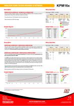
INSULATION GUARD FOR NON-GROUNDED AC NETWORKS Relay Operation (>6MΩ) This unit is used for hospital, industrial, marine and offshore installations. Start of monitoring function is delayed when auxiliary power is switched on (default 5 secs delay). Fail Safe The unit has minimum 150 mS detection time for any insulation fault. Direct connection up to 500V line voltage. Adjustments Trip level Delay WARNING: 0-1MΩ 0-30secs ALARM: 0-1MΩ 0,1-3secs Coloured sectors show recommended areas of settings: - Indicates alarm trip zone - Indicates warning trip zone - Indicates healthy zone Output table (example...
Open the catalog to page 2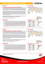
INSULATION GUARD FOR NON-GROUNDED AC NETWORKS Relay Operation (>2GΩ) Start of monitoring has a 30 secs delay. This unit is for marine, offshore, sub-sea and ocean floor use. It has a wide measuring range in order to detect degradation of insulation at its origin. An important feature is the unit’s unique inhibit function, controlled by the Load Distortion and Earth-capacitance Detector (LDED). The LDED function differentiates between a true (resistive) or a false (capacitive) drop in insulation reading, and will maintain reliable and accurate insulation monitoring even if load switching or a...
Open the catalog to page 3
INSULATION GUARD FOR NON-GROUNDED AC NETWORKS Start of monitoring has a 30 secs delay. This unit is for marine, offshore, sub-sea and ocean floor use. It has a wide measuring range in order to detect degradation of insulation at its origin. An important feature is the unit’s unique inhibit function, controlled by the Load Distortion and Earth-capacitance Detector (LDED). The LDED function differentiates between a true (resistive) or a false (capacitive) drop in insulation reading, and will maintain reliable and accurate insulation monitoring even if load switching or a major change in load spread...
Open the catalog to page 4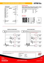
INSULATION GUARD FOR NON-GROUNDED AC NETWORKS KPM16x Analogue Output Relays shown de-energised, a fail-safe relay energises when unit is powered. Reset (only latching versions) KPM161F, KPM161GF, KPM163F, KPM163GF, KPM163H, KPM163HGF, KPM165HF, KPM165HGF, KPM165GF1, KPM165LF1, KPM165F1 and KPM165NF1 have an analogue output proportional to meter reading. (Special outputs are available on request) Add suffix from table below to type designation to specify output required: O/P1 0 - 10mA O/P6 N/A O/P2 0 - 20mA O/P7 N/A O/P3 4 - 20mA O/P8 0 - 10VDC O/P4 N/A O/P9 N/A O/P5 N/A O/P10 N/A Mounting Bracket...
Open the catalog to page 5All Meagacon AS catalogs and technical brochures
 MT-VA
MT-VA2 Pages
 MT-VF
MT-VF2 Pages
 MT-AW-R
3 Pages
 MT-FP
MT-FP2 Pages
 MT-FW/R
3 Pages
 MXG105 LOAD UNIT
1 Page
 MEVx Series
1 Page
 MCVBx Series
1 Page
 MEVx-0,2 Series
1 Page
 MCVBx-0,2 Series
1 Page
 MSA11B Series
1 Page
 MSA11E Series
1 Page
 MSA12B Series
1 Page
 KPM30x Series
2 Pages
 KPM303x Series
2 Pages
 KCT3x Series
1 Page
 FA Frequency Meter Series
5 Pages
 Integra Series
4 Pages
 PQ Voltmeter Series
6 Pages
 SADPminiEx Series
3 Pages
 SADPmini Series
4 Pages
 Switches F1Pxx Series
2 Pages
 D.C. DIN Shunts
2 Pages
 KCM165K
3 Pages
 KPM465x
3 Pages
 KPM26x
4 Pages
 KPM163FQ
2 Pages
 KPM161FQ
2 Pages
 K R M 1 6 1 - D C
1 Page
 KPM 16xM
3 Pages
 DC SIGNAL ISOLATOR
1 Page
 Voltage Comparator
1 Page
 SECTOR SYNCHRONISING RELAY
2 Pages
 GENERATOR CONTROLLER
2 Pages


- Measuring device
- Panel panel meter
- Protection relay
- Power meter
- Illuminated indicator
- LED indicator
- Monitoring relay
- Current protection relay
- DIN rail protection relay
- Digital protection relay
- Voltage protection relay
- Electric motor protection relay
- Three-phase protection relay
- DIN rail monitoring relay
- Panel-mount protection relay
- Current measuring module
- Voltage measuring module
- Overload relay
- Voltage monitoring relay
- Voltmeter