
- Catalogs
- Meagacon AS
- EMERGENCY/STANDBY GENERATOR MANAGEMENT SYSTEM KSQ304EG2

EMERGENCY/STANDBY GENERATOR MANAGEMENT SYSTEM KSQ304EG2

EMERGENCY/STANDBY GENERATOR MANAGEMENT SYSTEM KSQ304EG2
- Synchronising Modes: The system supports LEAD, LAG, and NEUTRAL modes for synchronisation, with a focus on maintaining stability and avoiding reverse power conditions.
- Speed Control: Utilizes a P/I characteristic with a dynamically controlled dead zone, adjustable pulse width, and rate for fuel regulator control.
- System Status: A relay indicates system status, activating under normal conditions and releasing during alarms or power loss.
- Operational Modes: Includes Frequency Control, Synchronising, Load Control, and Unload Generator modes, each with specific LED indicators and control signals.
Catalog excerpts
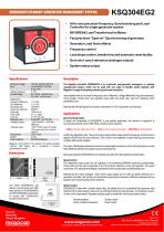
EMERGENCY/STANDBY GENERATOR MANAGEMENT SYSTEM KSQ304EG2 • All-in-one precision Frequency, Synchronising and Load Controller for single generator system • NO-BREAK Load Transfer back to Mains • Fast precision "Spot-on" Synchronising of generator • Generator Load Test to Mains • Frequency control • Load slope control, breaker trip and automatic reset facility • Generator speed reference (analogue output) • System status output Specifications Monitored Voltage Input: Voltage Tolerance: Contact Rating: Adjustments: Frequency difference: Volt differential: CB closing time: Frequency reference: Pulse rate: Pulse width: Load trim: Analogue input: *Analogue output: + 0,1-2Hz +/- 2-15% 30-300mS 48-62Hz 10-60 pr min 0,1 to 1,6secs 0-110% kW nom. 0-10mADC = 0-110% kW -10/0/+10mADC = -5/0/+5Hz difference -10/0/+10VDC (same Hz range) The digitally controlled KSQ304EG2 is an automatic one-generator emergency or standby management system, which can be used with any make of GenSet starter together with Megacon's range of standard protective guards and controllers. User settable limits on unit rear for frequency sync. difference, voltage differential, frequency reference, circuit breaker closing time, fuel regulator pulse width and pulse rate, load trim reference when parallelled to bus. Note that the kW load signal input must be calibrated to 0-110% of generator nominal load. Applications Synchronising modes To adapt the functionality of KSQ304EG2 to any specific application, the direction of approach to synchronising (LEAD, LAG or NEUTRAL) is factory set as required: *Optional output: LEAD (incomer faster than bus), LAG (incomer slower than bus), NEUTRAL (bi-directional) *Only active when Sync. mode is selected Temperature: Weight: Front protection: LEAD is the standard mode. The synchronising relay will then close when the frequency of the incomer is slightly HIGHER than the bus frequency. This avoids a non-stabilised incomer entering reverse power condition after synchronisation. Megacon is the inventor of the original, now industry standard “rotating” LED display, and a trendsetter in modern synchronisation control. The rotary LED display indicates the incomer's speed relative to the bus, and is lit during frequency mode if the difference between the systems does not exceeds 5Hz. Dimensions During all modes the UP/DOWN arrows indicate the pulses from the raise/lower speed relays. Mounting Bracket 11 12 13 14 15 16 17 18 19 20 Speed control The raise/lower relays pulse the fuel regulator or an interfacing MXR845x electronic potentiometer. Pulse width and rate can be adjusted to suit the dynamic response of any fuel regulator. The speed control has a P/I (proportional/integral) characteristic with a dynamically controlled dead zone. Mounting Bracket Alternatively the linear analogue -10/0/+10mA output signal can be used as speed reference to a generator controller, with polarity and amplitude proportional to frequency difference between the two systems when synchronising mode is selected. Unit meets IEC60092-504 and relevant environmental and EMC tests specified in IEC60068/60092 and IEC61000/60533 respectively, to comply with Classification Societies requirements. System status: KSQ304EG2 is fitted with a system status relay. As standard the unit is powered from generator side (terminal 3 & 4), when power is ok and unit is working correctly the relay activates. It will release on alarm or when unit is not powered. Separate auxiliary supply is needed for continuously system status. Normal operation Alarm condition/unpowered : Closed contact : Open contact Norway Denmark United Kingdom www.megacon.com ELECTRONIC CONTROL AND INSTRUMENTATION Page: 1 of 2 REF: Datasheet.KSQ304EG2 - REV: 1.04/03.2018 © All rights reserved to Megacon Megacon reserves the right to make any changes to the inf
Open the catalog to page 1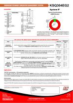
EMERGENCY/STANDBY GENERATOR MANAGEMENT SYSTEM "Spot-on" synchronising KSQ304EG2 11 1 CB close LEAD direction 12 2 Raise Breaker closing time Incomer (generator, busbar, etc.) System status 5 NOTE: Select a synchronising mode before using the unit. (see table for operation) Commen neg. + kW load input The breaker closure is initiated at “T” when the breaker coil is energised and finalises at “P”, assuring a precise “12 o'clock” synchronisation. Allowed frequency difference is adjustable between 0.1Hz to 2Hz. The angle “ ” varies according to the frequency difference between the two systems. The...
Open the catalog to page 2All Meagacon AS catalogs and technical brochures
 MT-VA
MT-VA2 Pages
 MT-VF
MT-VF2 Pages
 MT-AW-R
3 Pages
 MT-FP
MT-FP2 Pages
 MT-FW/R
3 Pages
 MXG105 LOAD UNIT
1 Page
 MEVx Series
1 Page
 MCVBx Series
1 Page
 MEVx-0,2 Series
1 Page
 MCVBx-0,2 Series
1 Page
 MSA11B Series
1 Page
 MSA11E Series
1 Page
 MSA12B Series
1 Page
 KPM30x Series
2 Pages
 KPM303x Series
2 Pages
 KCT3x Series
1 Page
 FA Frequency Meter Series
5 Pages
 Integra Series
4 Pages
 PQ Voltmeter Series
6 Pages
 SADPminiEx Series
3 Pages
 SADPmini Series
4 Pages
 Switches F1Pxx Series
2 Pages
 D.C. DIN Shunts
2 Pages
 KCM165K
3 Pages
 KPM465x
3 Pages
 KPM26x
4 Pages
 KPM163FQ
2 Pages
 KPM161FQ
2 Pages
 K R M 1 6 1 - D C
1 Page
 KPM 16xM
3 Pages
 K P M 1 6 x
5 Pages
 DC SIGNAL ISOLATOR
1 Page
 Voltage Comparator
1 Page
 SECTOR SYNCHRONISING RELAY
2 Pages
 GENERATOR CONTROLLER
2 Pages


- Measuring device
- Panel panel meter
- Protection relay
- Power meter
- Illuminated indicator
- Monitoring relay
- Current protection relay
- Digital protection relay
- Voltage protection relay
- DIN rail protection relay
- Three-phase protection relay
- Electric motor protection relay
- DIN rail monitoring relay
- Panel-mount protection relay
- Overload relay
- Current measuring module
- Voltage measuring module
- Phase protection relay
- Over-current protection relay