Safety Barriers - 1 / 2023
1 /32Pages

Safety Barriers - 1 / 2023
1 /32Pages
Catalog excerpts

Safety barriers
Open the catalog to page 1
The Profile System powered by Design Software The Tube Clamping System The Personnel Transfer System The Skid Transfer System The Dust Protection System Safety Barriers The Modular Wall System
Open the catalog to page 2
The Pipe & Joint System The Pipe & Joint System powered by Design Software The Pipe & Joint System The ideal modular system MayTec offers a comprehensive, harmonised modular system. All modules can be combined in any way conceivable. The accessories provide functional and aesthetic solutions for a wide range of applications. The MayTec service is as versatile as the MayTec modular system. You may choose: • delivery of standard elements ex-factory • delivery of profiles, pipes and accessories cut to size according to parts list for customer’s assembly • delivery of pre-fitted modular components...
Open the catalog to page 3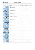
Summary: Catalogues Product Summary Design Software Design Software The Pipe & Joint System The Modular Wall System Safety Barriers The Tube Clamping System MayCAD / MayTube
Open the catalog to page 4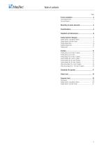
Table of contents Page
Open the catalog to page 5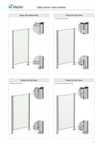
Safety barriers: Frame variations Design: Unit without frame Design: Unit with frame Fastening with brackets Design: Unit with frame Fastening with angles Design: Unit with frame Fastening with hanging brackets
Open the catalog to page 7
Safety barriers: Mounting of panel elements Panel element Frame profile Standard with wedge profile with mounting clamp blocks with mounting sockets Welded wire net (steel) with wedge profile
Open the catalog to page 8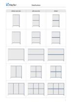
Classifications without cross strut with cross strut
Open the catalog to page 9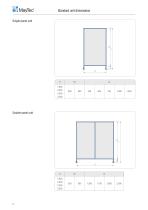
Standard unit dimensions Single panel unit Double panel unit
Open the catalog to page 10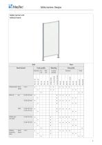
Safety barriers: Designs Safety barrier unit: without frame Welded wire net (steel) Post profile of panel element m. clamp blocks wedge profile Polycarbonate transparent Standard Panel
Open the catalog to page 11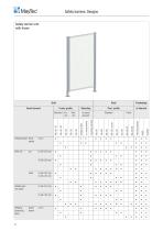
Safety barriers: Designs Safety barrier unit: with frame Welding protecting glass • Welded wire net (steel)
Open the catalog to page 12
Safety barriers: Designs Single hinged door • Welding protecting glass • Welded wire net (steel) Post profile of panel element m. clamp blocks
Open the catalog to page 13
Safety barriers: Designs Double hinged door Welding protecting glass • Welded wire net (steel)
Open the catalog to page 14
Safety barriers: Designs Sliding door • Welding protecting glass • Welded wire net (steel) Post profile
Open the catalog to page 15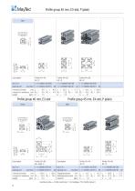
Profile group 40 mm, E3-slot, P (plain) core hole Ø5.0 for thread M6 core hole Ø12.0 for thread M14 Description bar, 6 m packing unit moment of inertia cm4 Ix = moment of resistance cm3 Wx = weight kg/m G = Profile group 45 mm, E4-slot, P (plain) light core hole Ø12.0 for thread M14 core hole Ø12.0 for thread M14 core hole Ø5.0 for thread M6 Description bar, 6 m packing unit Profile 80×80, 8E, angle, S 1.11.080080.87S.60 (number) 1.11.080080.87S.61 Description bar, 6 m (2) packing unit cm4 Ix = 13.5 Iy = 13.5 Ix = 98.0 Iy = 27.5 moment of inertia cm4 Ix = 120.0 Iy = 120.0 Trägheitsmoment moment...
Open the catalog to page 16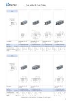
Panel profiles 30, F-slot, P (plain) core hole Ø12.0 for thread M14 Panel profile 30×30, 2F, corner, LP 4 moment of inertia cm4 Ix = moment of resistance cm3 Wx = weight kg/m G = Description bar, 6 m packing unit moment of inertia cm4 Ix = moment of resistance cm3 Wx = weight kg/m G = core hole Ø12.0 for thread M14 machining data ï Profile machining 1.1A (Catalogu
Open the catalog to page 17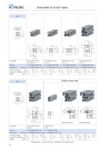
Panel profiles 40, E3-slot, P (plain) core hole Ø12.0 for thread M14 Panel profile 40×40, 2E, corner, LP 4 moment of inertia cm4 Ix = 10.3 Iy = 10.3 Ix = 10.2 Iy = moment of resistance cm3 Wx = 5.2 Wy = 5.2 Wx = 5.1 Wy = weight kg/m G = 1.8 G = 1.65 Profile for door stop core hole Ø12.0 for thread M14 Assembly drawing Description bar, 6 m packing unit moment of inertia cm4 Ix = 88.1 Iy = 52.0 Ix = moment of resistance cm3 Wx = 22.1 Wy = 17.3 Wx = weight kg/m G = 3.7 G = machining data ï Profile machining 1.1A (Catalogue 'The Profile Sys
Open the catalog to page 18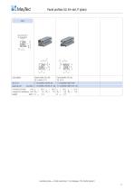
Panel profiles 50, E4-slot, P (plain) core hole Ø12.0 for thread M14 Description bar, 6 m packing unit Panel profile 50×50, 2E, corner, LP 4 moment of inertia cm4 Ix = 19.4 Iy = 19.4 Ix = 24.1 Iy = 21.4 moment of resistance cm3 Wx = 7.6 Wy = 7.6 Wx = 8.0 Wy = 8.5 weight kg/m G = 2.4 G = 2.7 machining data ï Profile machining 1.1A (Catalogue 'The Profile
Open the catalog to page 19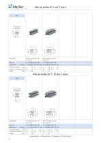
Wire net profiles 30, F-slot, P (plain) core hole Ø12.0 for thread M14 moment of inertia cm4 Ix = 2.6 Iy = moment of resistance cm3 Wx = 1.7 Wy = weight kg/m G = 0.86 Wire net profiles 40, F / E3-slot, P (plain) light core hole Ø12.0 for thread M14 Description bar, 6 m packing unit moment of inertia cm4 Ix = 7.5 Iy = moment of resistance cm3 Wx = 3.8 Wy = weight kg/m G = 1.35 machining data ï Profile machining 1.1A (Catalogue 'The
Open the catalog to page 20
Standards for guards Standards for guards Besides the essential safety requirements of the machinery directive 98/37/EC and the DIN EN ISO 12100 part 1+2 - safety of machinery - the following standards (Type B Standards) apply when designing guards, e.g. safety barriers. EN 294 - Safety distances to prevent danger zones being reached by the upper limbs The safety distances depend on the height and size of the opening in the safety guard. A mesh size of 40×40 mm requires a safety distance of 200 mm. The following figures show the safety distance profiles in accordance with EN 294 and EN 811 for...
Open the catalog to page 21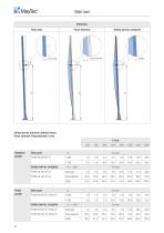
Static load Deflection Door post Panel element Safety barrier, complete Safety barrier element: without frame Panel element: Polycarbonate 4 mm F in N 100 Standard profile Door post Profile 40×80, 6E, LP Safety barrier, complete Door post Door post Profile 60×80, 6E, Panel, LP Panel element Panel profile Safety barrier, complete Door post Panel element
Open the catalog to page 22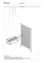
Dynamic load Test layout Test conditions During this test a body of 100 kg is accelerated to 20 km/h. During impact of the body into the test barrier an energy of 1600 Joule will be released. The impact zone is located at the upper third of the test barrier. 21
Open the catalog to page 23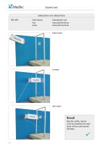
Dynamic load Safety barrier unit: without frame Test with: Panel element: Post: Frame: Panel profile 60×80 mm Panel profile 40×40 mm before impact after impact Result MayTec safety barrier units succeeded all crash tests without permanent damage.
Open the catalog to page 24All MayTec catalogs and technical brochures
 The Profile System - 1 / 2018
348 Pages
 The Telescopic System - 1 / 2023
12 Pages
 The Trailer System - 1 / 2023
24 Pages
 Arbeitsplatz Zubehör - 01 / 2022
24 Pages
 Pipe and Joint System - 1 / 2023
212 Pages
 The Conveyor System - 1 / 2023
88 Pages
 Modular Wall System - 1 / 2023
24 Pages
 MayCAD - 1 / 2023
8 Pages
 Noise Resist - 1 / 2023
24 Pages
 The Linear System - 1 / 2023
52 Pages
 Telescopic System
12 Pages


Archived catalogs
 Dusk Protection System
12 Pages
 Product Range
4 Pages
 The people Mover System
40 Pages
 The Linear System
48 Pages
 Curved Profiles
4 Pages
 Das Linear System - 2018
48 Pages
 Bent Profiles
4 Pages
 The Trailer System
24 Pages
 Product Summary - 1 / 2023
72 Pages
 Product summary
40 Pages
 Protective Barriers
12 Pages
 The Conveyer System
112 Pages
 Product summary
24 Pages
 Profile Catalogue
349 Pages
- AMOT industrial press
- Milling tool
- Solid milling cutter
- Screw
- Profile
- AMOT conveyor belt
- AMOT nut
- AMOT hinge
- Metal profile
- AMOT round plug
- AMOT metal hinge
- AMOT plastic plug
- AMOT metal nut
- AMOT metal handle
- AMOT swivel caster
- AMOT screw-in hinge
- AMOT machine foot
- AMOT industrial conveyor belt
- Industrial profile
- AMOT flush grid conveyor belt