The Profile System Inch - 01 / 2023
1 /44Pages

The Profile System Inch - 01 / 2023
1 /44Pages
Catalog excerpts

The Profile System Inch
Open the catalog to page 1
The Profile System powered by Design Software The Tube Clamping System The Personnel Transfer System The Skid Transfer System The Dust Protection System Safety Barriers The Modular Wall System
Open the catalog to page 2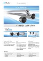
The Pipe & Joint System The Pipe & Joint System powered by Design Software The Pipe & Joint System The ideal modular system MayTec offers a comprehensive, harmonised modular system. All modules can be combined in any way conceivable. The accessories provide functional and aesthetic solutions for a wide range of applications. The MayTec service is as versatile as the MayTec modular system. You may choose: • delivery of standard elements ex-factory • delivery of profiles, pipes and accessories cut to size according to parts list for customer’s assembly • delivery of pre-fitted modular components...
Open the catalog to page 3
Summary: Catalogues Product Summary Design Software Design Software The Pipe & Joint System The Modular Wall System Safety Barriers The Tube Clamping System MayCAD / MayTube
Open the catalog to page 4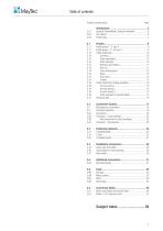
Table of contents Product number group
Open the catalog to page 5
Symbols, Abbreviations, Special characters General Profile group 1", 1.5" The profiles of the MayTec Profile System Inch are divided into two profile groups (PG). They can be determined by the basic measure of each profile. H-slot, F-slot, E-slot In order to connect the profiles or to mount accessories the profiles have slots. The MayTec Slot System (ï 2.02) distinguishes between the three slot types H-slot, F-slot and E-slot, whereas E-slot exists as E3-slot and E4-slot (3 or 4 mm resp. .118 or .157 in. wall thickness). The Profile System Inch uses only F-slot and E3-slot. Many articles (fastening elements,...
Open the catalog to page 7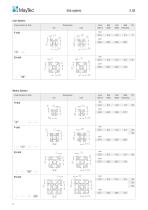
Slot system Inch-System Cross section of slots Wall thickness Core hole-Ø Slot width Slot depth Wall thickness Slot depth Slot width Metric-System Cross section of slots
Open the catalog to page 8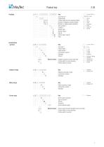
ääääää ääääää ääääää ääääää äää R ää ääää k t ääääää ääääää ääääää ääääää ääääää ääääää ääääää äääää äääää äääää äääää äääää äää V ä ääää E Key Core hole-Ø 1) Profile width Profile height (all, but special profiles) Number of degrees (round profiles) Number of edges (special profiles) Slot quantity 2) Contour 3) Version light Version heavy Type B Version light, Type B Plain Key Core hole 1) Profile width 2) Head-variant 3) Connection-variant 4) Stainless Ground E-head F-head H-head Extension Universal / Neutral Standard Standard 90° Square head Parallel Round Soft Corner Cubic Rectangle Angle Angle...
Open the catalog to page 9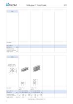
Profile group 1", F-slot, P (plain) Description bar, 19.685 ft. packing unit moment of inertia in.4 moment of resistance in.3 weight per foot lbs. core hole Ø .394 for thread M12 or 1/2" - 13 Description bar, 19.685 ft. packing unit moment of inertia in.4 Ix = .046 Iy = .046 Ix = .304 Iy = .086 moment of resistance in.3 Wx = .092 Wy = .092 Wx = .304 Wy = .172 weight per foot lbs. G = .497 G = .900 machining data ï Profile machining 1.1
Open the catalog to page 10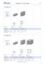
Profile group 1.5", E3-slot, P (plain) core hole Ø .394 for thread M12 or 1/2" - 13 Description bar, 19.685 ft. packing unit moment of inertia in.4 Ix = .180 Iy = .180 Ix = 1.217 Iy = .340 moment of resistance in.3 Wx = .237 Wy = .237 Wx = .813 Wy = .455 weight per foot lbs. G = .894 G = 1.557 core hole Ø .394 for thread M12 or 1/2" - 13 Description bar, 19.685 ft. packing unit moment of inertia in.4 Ix = .224 Iy = .224 Ix = 1.525 Iy = .436 Ix = 2.810 Iy = 2.810 moment of resistance in.3 Wx = .301 Wy = .301 Wx = 1.012 Wy = .583 Wx = 1.870 Wy = 1.870 weight per foot lbs. G = 1.121 G = 2.050 G =...
Open the catalog to page 11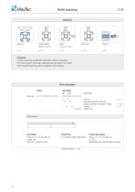
Profile machining Cross bushing bores for connectors ï 12 Cross bore Comments • Profile machinings are defined by the article-number of the profile. • For more complex machinings, additional order descriptions are needed. • Non-standard machinings will be completed as per drawings Order description Profile machining left right Order-No.: 2.11.ääääää.ääää - ääääää / ääää ääääää / ääää ääääää / ääää ääääää / ääää ääääää / ääää profile side saw cut cross bushing bores, bores for parallel-connector, cross bore, thread direction length in mm Order example Description Profile 1.5"×1.5", 4E-slots, SP Length:...
Open the catalog to page 12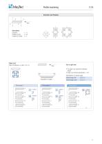
Profile machining Description Direction: Position of slot: Position of thread: • For angle cuts specify the absolute length • Angle cuts without specification = 45° Specification for special angle: Special angle, left: ää.ä° Special angle, right: ää.ä°
Open the catalog to page 13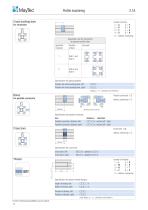
Profile machining Cross bushing bore Disposition rule for connectors at opposed profile sides Specified Direction Specification for special position: Position for cross bushing bore, left: Position for cross bushing bore, right: äää... äää... initials (ï 11, „Direction and Position“) without machining = 0 left distance right Direction data for anchor Specification for parallel-connector: text Parallel-connector, distance left: Parallel-connector, distance right: distance direction ää.ä in., anchor left / right ää.ä in., anchor left / right Cross bore Cross bore = Q without machining = 0 Specification...
Open the catalog to page 14All MayTec catalogs and technical brochures
 The Profile System - 1 / 2018
348 Pages
 The Telescopic System - 1 / 2023
12 Pages
 The Trailer System - 1 / 2023
24 Pages
 Arbeitsplatz Zubehör - 01 / 2022
24 Pages
 Pipe and Joint System - 1 / 2023
212 Pages
 The Conveyor System - 1 / 2023
88 Pages
 Modular Wall System - 1 / 2023
24 Pages
 Safety Barriers - 1 / 2023
32 Pages
 MayCAD - 1 / 2023
8 Pages
 Noise Resist - 1 / 2023
24 Pages
 The Linear System - 1 / 2023
52 Pages
 Telescopic System
12 Pages

Archived catalogs
 Dusk Protection System
12 Pages
 Product Range
4 Pages
 The people Mover System
40 Pages
 The Linear System
48 Pages
 Curved Profiles
4 Pages
 Das Linear System - 2018
48 Pages
 Bent Profiles
4 Pages
 The Trailer System
24 Pages
 Product Summary - 1 / 2023
72 Pages
 Product summary
40 Pages
 Protective Barriers
12 Pages
 The Conveyer System
112 Pages
 Product summary
24 Pages
 Profile Catalogue
349 Pages
- AMOT industrial press
- Milling tool
- Solid milling cutter
- Screw
- Profile
- AMOT conveyor belt
- AMOT nut
- AMOT hinge
- Metal profile
- AMOT round plug
- AMOT metal hinge
- AMOT plastic plug
- AMOT metal nut
- AMOT metal handle
- AMOT swivel caster
- AMOT screw-in hinge
- AMOT machine foot
- AMOT industrial conveyor belt
- Industrial profile
- AMOT flush grid conveyor belt