


The Profile System - 1 / 2018

The Profile System - 1 / 2018
MayTec offers a versatile profile system with a wide range of accessories for various applications, providing both functional and aesthetic solutions.
MayTec provides flexible services including delivery of standard elements, custom-sized profiles, pre-fitted components, fully assembled units, and on-site assembly.
The profile system is designed for easy processing and quick assembly, with modular construction allowing modifications and reusability. An experienced team supports tailored implementation.
Details on profile groups categorized by size and slot type, technical data, machining options, and application examples are provided.
Outlines connector selection, types, connection possibilities, and strength values, with examples for different profile systems.
Includes fastening elements, installation accessories, pneumatic and electrical accessories, panel elements, and tools, with specific components detailed.
MayTec offers free CAD design software for quick design and export of 3D models and parts lists.
Includes tensile strength, pressure tension, stress points, E-Module, Brinell hardness, and coefficient of elongation.
Profiles made from Aluminium alloy AI Mg Si 0.5 F25, following DIN EN 12020 standards, with anodised surface treatment.
Defined by DIN EN 12020-2, with nominal dimension deviations and flatness and straightness tolerances specified.
Profiles designed with concave surfaces for tension maintenance, with straightness tolerance specified.
Deflection calculated using specific formulas, with example calculations for different load types.
Profiles categorized by dimensions and design, with data on moments of inertia, resistance, and weight.
MayTec Connector System allows stable profile combinations, with special slits for panel elements.
Designed for balustrades with options for straight, angled, and tilted configurations.
Used for constructing height-adjustable frames, with specific weights and article numbers.
Profiles for cable guides with open slots, detailed slot distances, and machining data.
Technical specifications for various profile types and applications.
Designed for stability and ease of assembly, with universal, standard, screw-type, and ground connectors.
Connectors available with or without machining, with detailed procedures for manufacturing connections.
Specifications and instructions for connectors used with profiles having core hole diameters of 6 mm and 12 mm.
- Connectors for profiles with core hole diameters of 6 mm and 12 mm.
- Materials include standard steel and stainless steel.
- Universal, screw-type, and special connectors for various applications.
- Instructions for screw-type connectors and miter joints.
- Use specified drills for miter anchors and consider ordering parts separately.
- Article numbers for each connector type for easy identification and ordering.
Comprehensive guide for selecting and installing connectors for profiles with specific core hole diameters.
Details on threaded inserts, cover profiles, sliding and cover profiles, reducing profiles, combination profiles, framing profiles, wedge profiles, sponge rubber round cords, sealing profiles, rubber cover-profiles, cover caps, and cover plugs.
Used for closing connector cross bushing bores and aluminum tubes, with technical specifications provided.
Designed for covering exterior profile radii, with detailed specifications.
Used for adjusting the height of structures, with specifications for different types.
Used for height adjustment, with specific static load capacities.
Essential for assembly of adjustable tilt-feet, with technical data provided.
Designed to prevent dislocation and floor damage, with specifications provided.
Used for fastening frames to floors or walls, with specifications provided.
Specifications and descriptions of various installation accessories, including base feet, mounting sets, castors, and angles.
- Used for fastening profiles and frames to floors or walls, with materials and article numbers provided.
- Available for different profile sizes, with technical specifications provided.
- Fixed and swivel castors available, with materials and load capacities specified.
- Used for supporting profiles and mounting panels, with materials and technical data provided.
- Designed for easy movement and positioning, with materials and load capacities detailed.
Comprehensive guide for selecting and using installation accessories.
Specifications and technical data for various installation accessories used in mechanical and structural applications.
- Different angle connection sets made from GD-Al, with technical data provided.
- Allow for adjustable inclination, with technical data provided.
- Enable profile adjustment in two directions, with technical data provided.
- Used for fastening and leveling profiles, with technical data provided.
- Used for fastening and leveling profile racks, with technical data provided.
- Used for connecting profiles and fastening accessories, with technical data provided.
- Increase carrying capacity of brackets or swivel arms, with technical data provided.
- Used for transferring frames and equipment, with technical data provided.
- Used for connecting profiles, with technical data provided.
- Details on pneumatic end plates and profiles, with technical data provided.
Available in various sizes, with components and specifications provided.
Facilitate air pressure inlet and exhaust, with specifications provided.
Designed for extending air-pressurized profiles, with specifications provided.
Enable 90° connections of air-pressurized profiles, with specifications provided.
Includes blanking plugs, reducing nipples, and sealing rings, with specifications provided.
Various handles available, with materials and mounting options provided.
Available for doors and flaps, with materials and load capacities provided.
Specifications and applications for various types of hinges and joints used in door and profile connections.
- Materials, surface, hinge bolt, and max static load provided.
- Hinges used for connecting profiles and doors, with specific applications provided.
- Hinges available in various sizes and weights, with article numbers provided.
- Allow for variable adjusting and swivelling of profiles, with materials and max loads provided.
- Mounting instructions and additional accessories provided.
Specifications and descriptions of various mounting blocks, clamps, locks, and accessories used for panel mounting and door locking systems.
- Various types available, with materials and technical data provided.
- Designed for panel mounting without drilling, with materials and load capacities provided.
- Includes bullet catches, magnetic locks, and cylinder locks, with technical specifications provided.
- Quick locks and various bolts and washers provided, with technical data provided.
- Materials, temperature ranges, and hardness specifications provided.
Specifications and descriptions of various locking mechanisms and accessories used in door systems.
- Models listed with weights and article numbers provided.
- Described for doors with profile frames, with technical data provided.
- Designed for large doors, with technical data provided.
- Used for guiding sliding doors, with technical data provided.
- Includes runners, stoppers, and C-tracks, with technical data provided.
Comprehensive guide for selecting and installing various door locking and sliding mechanisms.
Specifications and descriptions of various tools and components used in machining and assembly processes.
Lists tools with technical data, including material composition, dimensions, weight, and article numbers.
Outlines application of tools in precise machining tasks.
Emphasizes use of specific tools for particular applications, with technical data provided.
Includes tables listing tools with dimensions, weights, and article numbers.
Tools categorized based on applications, with use of screw taps for creating threads in aluminum profiles.
Highlights importance of selecting the right tool, with comprehensive index for easy navigation.
Catalog excerpts

MayTec System Technology Solutions with Innovative Profile The Modular Wall System The Tube Clamping System The People Mover System The Skid Transfer System Safety Barriers The Dust Protection System The Pipe & Joint System The ideal profile system MayTec offers a comprehensive, harmonised profile system. All profiles can be combined in any way conceivable. The accessories provide functional and aesthetic solutions for a wide range of applications. The MayTec service is as versatile as the MayTec profile system. You may choose: • delivery of standard elements ex-factory • delivery of profiles and accessories...
Open the catalog to page 2
Profiles Summary Profile selection range 1.1D Washers, screws and tools 1.9 Subject index
Open the catalog to page 3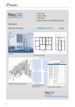
Design Software • Free to use • Easy to install • 80% Faster • Export function for 3D models and parts list Sample Machine enclosure Exploded view with part numbers Dimensional drawing Detailed drawings for all panel elements Parts list with calcula ons
Open the catalog to page 4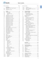
Table of contents Article number group Page Article number group Page 1.2E Specification of milling patterns for closed profiles 123
Open the catalog to page 5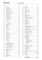
Table of contents Article number group Page Article number group Page
Open the catalog to page 6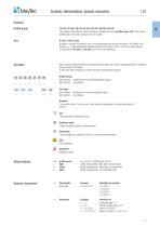
Symbols, Abbreviations, Special characters 1.01 GeneralProfile group Slot 16 mm, 20 mm, 30 mm, 40 mm, 45 mm, 50 mm, 60 mm The profiles of the MayTec Profile System are divided into seven profile groups (PG). They can be determined by the basic measure of each profile. H-slot, F-slot, E-slot In order to connect the profiles or to mount accessories the profiles have slots. The MayTec Slot System (^ 1.02) distinguishes between the three slot types H-slot, F-slot and E-slot, whereas E-slot exists as E3-slot and E4-slot (3 or 4 mm wall thickness). Symbols Many articles (fastening elements, accessories...
Open the catalog to page 7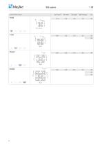
Cross section of slots Core hole-0 Slot width Slot depth Wall thickness PG
Open the catalog to page 8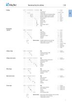
i MayTec Numerical key for articles 1.03 1. 1 □ . □ □□□□□ . □□□□□ 1. 1 □ . □□□□□□ . □□□□□ 1. 1 □ . □ □□□□□ . □□□□□ 1. 1 □ . □□□□□□ . □□□□□ 1. 1 □ . □□□ R □□ . □□□□□ 1. 1 □ . □□□□□□ . □□□□□ 1. 1 □ . □□□□□□ . □□□□□ 1. 1 □ . □□□□□□ . □□ L Key Core hole-0 11 Profile width Profile height (all, but special profiles) Number of degrees (round profiles) Number of edges (special profiles) Slot quantity 2) Contour 3) Version light Version heavy Type B Version light, Type B Plain Connectors - general 1. 2 □ . □ □□□□ 1. 2 □ . □□□□□ 1. 2 □ . □□□□□ 1. 2 □ . □ □□□□ 1. 2 □ . □□□□□ 1....
Open the catalog to page 9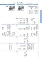
ayTec Summary: Profiles without grooves with grooves L
Open the catalog to page 11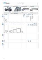
Summary: Profiles Profiles octagonal Telescopic profiles Panel bazel profiles Panel profiles ï "The Telescopic System" 30 octag.
Open the catalog to page 12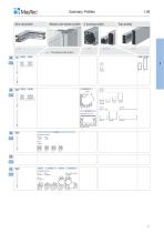
Summary: Profiles Wire net profiles Modular wall system profiles E-trunking profiles Tube profiles ï "The Modular Wall System" 30×30
Open the catalog to page 13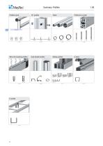
Summary: Profiles Profiles round Profile pre-cut lids Wire net mounting profiles Grab handle profiles Sliding profiles
Open the catalog to page 14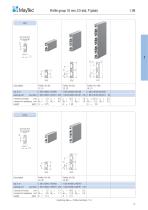
Profile group 16 mm, E3-slot, P (plain) 1.09 bore hole 05.0 for thread M6 Description bar, 6 m packing unit moment of inertia cm4 moment of resistance cm3 weight kg/m bore hole 05.0 for thread M6 bar, 6 m packing unit (number) moment of inertia cm4 moment of resistance cm3 weight kg/m machining data ^ Profile machining 1.1A
Open the catalog to page 15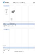
Profile group 16 mm, F-slot, P (plain) core hole Ø6.2 for thread M8 moment of inertia cm4 Ix = 4.4 Iy = moment of resistance cm3 Wx = 2.2 Wy = weight kg/m G = 0.87 Description bar, 6 m packing unit moment of inertia cm4 moment of resistance cm3 weight kg/m machining data ï Profile machining 1.1A 14
Open the catalog to page 16
Profile group 20 mm, H-slot, P (plain) core hole Ø6.2 for thread M8 moment of inertia cm4 moment of resistance cm3 weight kg/m core hole Ø6.2 for thread M8 Description bar, 6 m packing unit moment of inertia cm4 Ix = 0.6 Iy = moment of resistance cm3 Wx = 0.6 Wy = weight kg/m G = 0.52 machining data ï Profile m
Open the catalog to page 17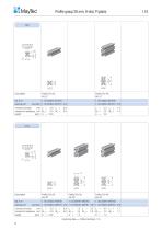
Profile group 20 mm, H-slot, P (plain) core hole Ø6.2 for thread M8 moment of inertia cm4 Ix = 0.8 Iy = moment of resistance cm3 Wx = 0.8 Wy = weight kg/m G = 0.53 core hole Ø6.2 for thread M8 Description bar, 6 m packing unit moment of inertia cm4 Ix = 0.9 Iy = moment of resistance cm3 Wx = 0.9 Wy = weight kg/m G = 0.62 machining data ï Profile machining 1.1A 16
Open the catalog to page 18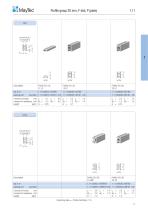
Profile group 20 mm, F-slot, P (plain) core hole Ø12.0 for thread M14 Description bar, 6 m packing unit moment of inertia cm4 Ix = 0.1 Iy = moment of resistance cm3 Wx = 0.2 Wy = weight kg/m G = 0.35 core hole Ø12.0 for thread M14 moment of inertia cm4 moment of resistance cm3 weight kg/m machining data ï Profil
Open the catalog to page 19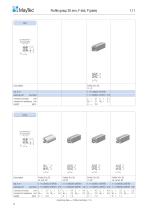
machining data ^ Profile machining 1.1A
Open the catalog to page 20
i MayTec Profile group 30 mm, F-slot, P (plain) 1.11 machining data ^ Profile machining 1.1A
Open the catalog to page 21
moment of inertia cm4 moment of resistance cm3 weight kg/m machining data ^ Profile machining 1.1A
Open the catalog to page 22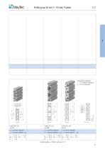
machining data ^ Profile machining 1.1A
Open the catalog to page 23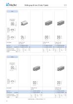
Profile group 40 mm, E3-slot, P (plain) bore hole Ø5.0 for thread M6 bore hole Ø5.0 for thread M6 core hole Ø12.0 for thread M14 Description bar, 6 m packing unit Profile 40×40, 2E, soft, LP 1.11.040040.21LP.60 (number) 1.11.040040.21LP.61 moment of inertia cm4 Ix = moment of resistance cm3 Wx = weight kg/m G = bore hole Ø5.0 for thread M6 core hole Ø12.0 for thread M14 moment of inertia cm4 moment of resistance cm3 weight kg/m
Open the catalog to page 24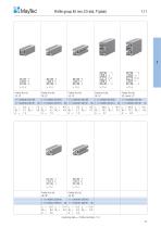
Profile group 40 mm, E3-slot, P (plain)
Open the catalog to page 25
Profile group 40 mm, E3-slot, P (plain) bore hole Ø5.0 for thread M6 bore hole Ø5.0 for thread M6 core hole Ø12.0 for thread M14 Description bar, 6 m packing unit moment of inertia cm4 Ix = 65.8 Iy = 18.1 Ix = 74.5 Iy = 18.3 Ix = 72.2 Iy = 18.1 Ix = 65.4 Iy = 17.5 moment of resistance cm3 Wx = 16.5 Wy = 9.0 Wx = 18.6 Wy = 9.2 Wx = 18.0 Wy = 9.0 Wx = 16.4 Wy = 8.8 weight kg/m G = 2.6 G = 2.8 G = 2.8 G = 2.5 bore hole Ø5.0 for thread M6 core hole Ø12.0 for thread M14 moment of inertia cm4 moment of resistance cm3 weight kg/m
Open the catalog to page 26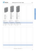
H MayTec 1.11 Profile group 40 mm, E3-slot, P (plain)
Open the catalog to page 27All MayTec catalogs and technical brochures
 The Telescopic System - 1 / 2023
12 Pages
 The Trailer System - 1 / 2023
24 Pages
 Arbeitsplatz Zubehör - 01 / 2022
24 Pages
 Pipe and Joint System - 1 / 2023
212 Pages
 The Conveyor System - 1 / 2023
88 Pages
 Modular Wall System - 1 / 2023
24 Pages
 Safety Barriers - 1 / 2023
32 Pages
 MayCAD - 1 / 2023
8 Pages
 Noise Resist - 1 / 2023
24 Pages
 The Linear System - 1 / 2023
52 Pages
 Telescopic System
12 Pages


Archived catalogs
 Dusk Protection System
12 Pages
 Product Range
4 Pages
 The people Mover System
40 Pages
 The Linear System
48 Pages
 Curved Profiles
4 Pages
 Das Linear System - 2018
48 Pages
 Bent Profiles
4 Pages
 The Trailer System
24 Pages
 Product Summary - 1 / 2023
72 Pages
 Product summary
40 Pages
 Protective Barriers
12 Pages
 The Conveyer System
112 Pages
 Product summary
24 Pages
 Profile Catalogue
349 Pages