The Linear System

The Linear System
The MayTec Linear System is designed for integration with components from well-known bearing manufacturers, offering a modular and flexible solution for linear guidance technology. It supports various configurations, including individual components, pre-fitted modular units, and complete systems, with options for on-site assembly.
Performance and Application
The system's modularity allows for economical and functional solutions with minimal effort. It is easy to assemble, modify, and reuse, making it suitable for various applications. Configurations are based on dimensions, expected forces, and required stability.
Encased Roller Bearings and Shaft Guidance
Encased roller bearings are suitable for both low and high load applications, offering high force tolerance, low wear, and high accuracy. Shaft guidance systems provide compact, stable, and accurate solutions, with options for sliding or ball bearing guides.
Numerical Key for Articles
The document provides a numerical key for identifying components of the linear system, including linear units, drive units, and turning units, categorized by size, orientation, material, and other specifications.
Linear Units and Components
Linear units are available with toothed belt drives and various guide options, including wheel and ball bearing guides. Dimensions and specifications for each component, such as width, height, and length, are outlined.
Design and Selection
The design section details options for linear shaft guidance, including single and double-sided shafts, and various profile designs. A selection table provides detailed specifications for different linear unit configurations, including dimensions, belt types, and carriage details.
Conclusion
The MayTec Linear System offers a comprehensive and adaptable solution for linear guidance needs, focusing on modularity, ease of use, and integration with existing systems.
Specifications
The document lists dimensions, shaft guidance diameters, drive unit widths, belt widths, and heights from shaft center to upper edge of carriage. It also includes widths of carriages, center distances from ball bearings to carriages, and clear widths of carriages.
Technical Data
Each linear unit is described with its article number, dimensions, and technical parameters such as moment of inertia, pinion diameter of turning units, and tooth numbers of pinions. The document distinguishes between returns of belts outside and inside.
Selection Table
The selection table is organized by article numbers and includes detailed measurements for each linear unit configuration, providing data on dimensions and technical specifications necessary for selecting the appropriate linear unit for specific applications.
Key Parameters
Critical parameters include the diameter of shaft guidance, width of drive units, belt widths, and heights from shaft centers to upper edges of carriages, crucial for ensuring compatibility and performance in various mechanical setups.
Applications
The linear units are suitable for applications requiring precise linear motion control, such as in automation systems, machinery, and robotics. The document provides a comprehensive guide for selecting the right unit based on specific technical requirements.
Catalog excerpts
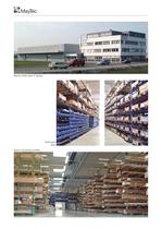
MayTec GmbH plant in Dachau Stock of aluminium profilesSmall partsstore >
Open the catalog to page 2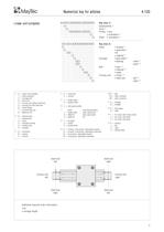
4.1 . . . Key (line 1) 4.1 . . .4.1 Subassembly > 1) . . .4.1 Drive > 2) . . .4.1 Profile sizeՕ orientation . . .4.1 > 3) . . . Shaft orientation > 4) . . Key (line 2) . . ShaftՕ number > 5) . . assembly > 6) . . Օ ؕ material . . > 7) . . Carriage base plate > 8) . . Օ bearing- roller > 9) . . - bush > 10) . . Belt type > 11) . . Օ material > 12) . . widthTurning unitՕ motor . . > 13) . . shaft end- left > 14) . . - right > 14) 1) 0=linear unit complete 1=linear guidance 2=carriage unit 3=drive unit 4=turning unit without shaft end 5=turning unit with shaft end 6=motor flange 7=syncronising unit...
Open the catalog to page 5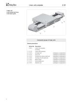
with toothed belt driveՕ with wheel guide > Ordering description:Article-No.Description 4.101...Linear unit completeincluding: 4.119...Linear shaft guidance 4.121...Carriage unit(catalogue in preparation) 4.131...Drive unit(catalogue in preparation) 4.141...Turning unit without shaft end(catalogue in preparation) 4.151...Turning unit with shaft end(catalogue in preparation) 4.161...Motor flange(catalogue in preparation) 4.171...Syncronising unit(catalogue in preparation) 4.181...Gearbox unit(catalogue in preparation) > 4 size="-1">
Open the catalog to page 6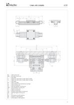
AB=width of drive unitARB=belt width of drive unitH=total heigthH1=heigth from shaft center to upper edge of profileH2=heigth from shaft center to upper edge of carriageL=total lengthSB=width of carriageSC=center distance from ball bearing to carriageUB=width of turning unitUD=shaft end diameter of turning unitUDR=pinion diameter of turning unitUH=heigth of turning unitUL=length of turning unitUPL=parabolic spring length of turning unitUW=shaft end length of turning unitW=liftWa=axle distance of shaft guidanceWD=diameter of shaft guidanceWL=profile length of shaft guidance 5 >
Open the catalog to page 7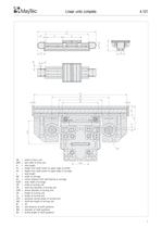
AB=width of drive unitARB=belt width of drive unitH=total heigthH1=heigth from shaft center to upper edge of profileH2=heigth from shaft center to upper edge of carriageL=total lengthSB=width of carriageSC=center distance from ball bearing to carriageSLW=clear width of carriageUB=width of turning unitUD=shaft end diameter of turning unitUDR=pinion diameter of turning unitUH=heigth of turning unitUL=length of turning unitUPL=parabolic spring length of turning unitUW=shaft end length of turning unitW=liftWa=axle distance of shaft guidanceWD=diameter of shaft guidanceWL=profile length of shaft guidance...
Open the catalog to page 9
Shaft-:121620 25Single sided shaft Double sided shaft Frame designSingle profile design horizontalvertical horizontalvertical > Base plateAlu plateBearingShaft-ؘ:121620 25 Profile 30150RollerSliding or ball bearing guidesProfiles 30ח60, 30150 1 piece2 pieces3 pieces fixedeccentric > adjustable topsideadjustable underside 8 >
Open the catalog to page 10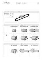
Type of toothed belt:5M8M width of toothed belt:1520253050 > Size:60100150 for motor with hollow shaftfor motor with shaft and flangefor motor with shaft and base without shaftwith sigle sided shaftwith double sided shaft > Motor with hollow shaftMotor with shaft and flangeMotor with shaft and base 9 >
Open the catalog to page 11
4.119.00. . . . / Key 4.119.00. . . . / Profile dimensionՕ orientation 4.119.00. . . . / > 1) 4.119.00. . . . / Shaft orientation > 2) 4.119.00. . . . / Օ number > 3) 4.119.00. . . . / assembly > 4) 4.119.00. . . . / Օ ؕ material 4.119.00. . . . / > 5) 4.119.00. . . . / Length > 1) H=horizontalN=neutral V=vertical 2) H=horizontal V=vertical 3) 1=single sided 2=double sided 4) 2=with guide profile 5) Shaftmounting elements1=tempering steelsteel, galvanised 2=X46Cr13steel, galvanised 3=X46Cr13VA 19 >
Open the catalog to page 21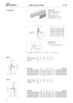
Technical data material:Al Mg Si 0,5 F 25surface:neutral anodisedlength:6 mheight and side tolerance:ؕ to specified length: 0.2 mmѕ within one bar:0.1 mm Cut to length:4.119.0 > countersinkDIN 74 - M6 Calculation of C1: C1 = 1/2(L-n120)n = maximum number of divisions .20. -02/...( /... = length in mm) > Moment of inertiacm > 4 Moment of resistancecm > 3 Weight (G)kg/mIx=14.6Iy=8.4Wx=4.0Wy=2.8 Moment of inertiacm DescriptionAaBbGArticle-No. Shaft guidance profile 20A37-37-1.74.119.0A.20.37003700.60 Shaft guidance profile 20A3720.03720.01.74.119.0A.20.37203720.60 Shaft guidance profile 20A3722.53722.51.74.119.0A.20.37223722.60...
Open the catalog to page 40
Technical data material:Al Mg Si 0,5 F 25surface:neutral anodisedlength:6 mheight and side tolerance:ؕ to specified length: 0.2 mmѕ within one bar:0.1 mm Cut to length:4.119.0 > countersinkDIN 74 - M6 Calculation of C1: C1 = 1/2(L-n120)n = maximum number of divisions .25. -02/...( /... = length in mm) > Moment of inertiacm > 4 Moment of resistancecm > 3 Weight (G)kg/mIx=16.6Iy=8.7Wx=4.4Wy=2.9 Moment of inertiacm DescriptionAaBbGArticle-No. Shaft guidance profile 25A37-37-1.94.119.0A.25.37003700.60 Shaft guidance profile 25A3720.03720.01.94.119.0A.25.37203720.60 Shaft guidance profile 25A3722.53722.51.94.119.0A.25.37223722.60...
Open the catalog to page 41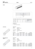
Dd1d2d3geC > 1) 1 min 1) G > For applications with axialthread C1 has to be adapted for the drilling depth of the axial thread 12 mmM5M4582.01012016 mmM6M5692.510150 20 mmM8M67113.01015025 mmM10M89153.015150 > 42 Calculation of C1: C1 = 1/2(L-nG)n = maximum number of divisions >
Open the catalog to page 43
Description Machining of shaft - 1 axial threadMachining of shaft - 2 axial threadsMachining of shaft - 1 axial and radial threadMachining of shaft - 2 axial and radial threads > Dd1d2d3geC > 1) 1 min 1) G > For applications with axialthread C1 has to be adapted for the drilling depth of the axial thread 12 mmM5M4582.01012016 mmM6M5692.51015020 mmM8M67113.01015025 mmM10M89153.015150 Calculation of C1: C1 = 1/2(L-nG)n = maximum number of divisions >
Open the catalog to page 44
bar 6 m 4.119.0W.11.12.60 cut to length 4.119.0W.11.12 / 4.119.0W.11.12֖ S / cut 4.119.0W.11.12 F / leftchamfer 4.119.0W.11.12֖ A / leftaxial thread 4.119.0W.11.12 F / rightchamfer 4.119.0W.11.12֖ A / rightaxial thread 4.119.0W.11.12 / length in mm 43 >
Open the catalog to page 45
Application samplesApplication samplesApplication samplesApplication samplesApplication samples 4.A4.A4.A4.A4.A > Linear unitLinear unitLinear unitLinear unitLinear unit toothed belt driveՕshaft guidance turning unit with primary shaft onone side Measuring systemMeasuring systemMeasuring systemMeasuring systemMeasuring system 44 size="-3">
Open the catalog to page 46All MayTec catalogs and technical brochures
 The Profile System - 1 / 2018
348 Pages
 The Telescopic System - 1 / 2023
12 Pages
 The Trailer System - 1 / 2023
24 Pages
 Arbeitsplatz Zubehör - 01 / 2022
24 Pages
 Pipe and Joint System - 1 / 2023
212 Pages
 The Conveyor System - 1 / 2023
88 Pages
 Modular Wall System - 1 / 2023
24 Pages
 Safety Barriers - 1 / 2023
32 Pages
 MayCAD - 1 / 2023
8 Pages
 Noise Resist - 1 / 2023
24 Pages
 The Linear System - 1 / 2023
52 Pages
 Telescopic System
12 Pages


Archived catalogs
 Dusk Protection System
12 Pages
 Product Range
4 Pages
 The people Mover System
40 Pages
 Curved Profiles
4 Pages
 Das Linear System - 2018
48 Pages
 Bent Profiles
4 Pages
 The Trailer System
24 Pages
 Product Summary - 1 / 2023
72 Pages
 Product summary
40 Pages
 Protective Barriers
12 Pages
 The Conveyer System
112 Pages
 Product summary
24 Pages
 Profile Catalogue
349 Pages
- AMOT industrial press
- Milling tool
- Solid milling cutter
- Screw
- AMOT conveyor belt
- AMOT nut
- AMOT hinge
- Metal profile
- AMOT round plug
- AMOT metal hinge
- AMOT plastic plug
- AMOT metal nut
- AMOT metal handle
- AMOT swivel caster
- AMOT screw-in hinge
- AMOT machine foot
- AMOT industrial conveyor belt
- Industrial profile
- AMOT flush grid conveyor belt