
Catalog excerpts
Polymer Electric Product information Safety Mats SM11 GmbH & Co. KG Polymer Electric Örlinger Straße 1–3 89073 Ulm GERMANY Tel.: +49 731 2061-0 Fax: +49 731 2061-222 E-Mail: info.ulm@mayser.com Internet: www.mayser.com
Open the catalog to page 1
Important information Read through the product information carefully. It contains important information on operation, safety and maintenance of the product. Retain the product information for later reference. Always observe the safety instructions on the following pages under ATTENTION. Only use the product for the purpose described in the product information. © Mayser Ulm 2013
Open the catalog to page 2
Definitions See Definitions and Operation Principles in chapter 1 of the catalogue. Intended use A safety mat detects a person that is standing on or stepping onto it. It is a protective device covering a certain area and monitoring the presence of a person on it as a safety function. Its purpose is to prevent possible hazardous situations for personnel within a danger zone. Typical applications are in the area of moving units on machines and plants. Safe operation of a safety mat depends entirely on - the surface condition of the mounting surface, - the correct selection of size and...
Open the catalog to page 3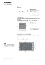
Design Standard version moulded onto a plastic plate; fitted in the factory with a non-slip structured surface non-slip category: R9 Degree of protection: IP65 Available sizes Sensors are available exclusively in rectangular shape up to a size of max.1.5 m2. The side lengths must be within a range of 200 to 3,000 mm. L1: cable side L2: not cable side L1 × L2 ≤ 1,5 m2 The cable exit can be on the wide or the narrow side. Non-sensitive zone along edges The surrounding area of a sensor which does not have a sensing function: - 40 mm = on cable exit side - 10 mm = on remaining three sides Note...
Open the catalog to page 4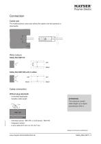
Polymer Electric Cable exit The multifunctional cutout also allows the cable to be laid upwards or Wire colours Safety Mat SM11/BK with 2 cables Cable connection Without plug (standard) - Universally applicable - Variable cable length Individual sensor SM11/W or end sensor SM11/W Integrated resistor cable length up to signal Subject to technical modifications.
Open the catalog to page 5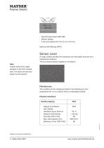
- Feed-through sensor SM11/BK - Without resistor - 2 two-wire cables (Ø 5 mm; 2× 0.5 mm2 Cu) Optional with M8 plug (IP67). Sensor cover A rough surface provides the necessary non-slip quality and acts as a mechanical protection. The structured surface is applied in the factory. Note Initially there will be slight abrasion in the form of black dust. This does not have any impact on the function. Resistances The condition for the resistances listed in the following (at room temperature 23 °C) is a sensor with an undamaged surface. Physical resistance Surface topping Degree of protection...
Open the catalog to page 6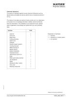
Chemical resistance The sensor is resistant against normal chemical influences such as diluted acids and alkalis as well as alcohol over an exposure period of 24 hrs. The values in the table are results of tests carried out in our laboratory to the best of our knowledge and belief. Liability cannot be derived from this information. The suitability of our products for your special area of application must always be verified with your own practical tests. Surface Explanation of symbols: + = resistant ± = resistant to a certain extent - = not resistant Acetone Ammonia Brake fluid Cutting...
Open the catalog to page 7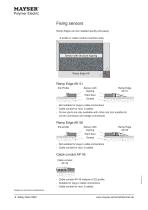
Polymer Electric Fixing sensors Ramp Edges can be installed quickly and easily. Z-profile or cable conduit (machine side) Sensor with structure topping Subject to technical modifications. Ramp Edge Plant floor Tlt?^^^. Screed ^^s>^>>?^>^ Not suitable for plug-in cable connections Cable conduit for max. 2 cables Corner joints are only available with mitre cuts (not suitable for corner connectors and wedge connectors) Plant floor Ramp Edge - Not suitable for plug-in cable connections - Cable conduit for max. 6 cables Cable conduit Cable conduit AP 45 instead of Z/2-profile Suitable for...
Open the catalog to page 8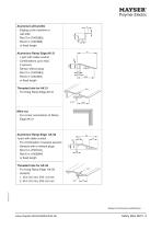
Aluminium-Z/2-profile - Edging at the machine or wall side - Rod 3 m (7500385), Rod 6 m (1001666) or fixed length Aluminium Ramp Edge AK 51 - 1-part with cable conduit - Combinations up to max. 2 sensors - Sensor without plug - Rod 3 m (7500384), Rod 6 m (1001667) or fixed length Threaded hole for AK 51 - For fixing Ramp Edge AK 51 Mitre cut - For corner connections of Ramp Edge AK 51 Aluminium Ramp Edge AK 56 1-part with cable conduit - For combination of several sensors - Sensors with or without plugs - Rod 3 m (7501014), Rod 6 m (1002684) or fixed length Threaded hole for AK 56 - For...
Open the catalog to page 9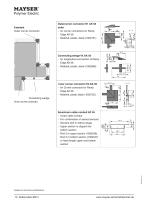
Example Outer corner connector Outercorner connector E1 AK 56 outer - for corner connectors for Ramp Edge AK 56 - Material: plastic, black (1002751) Connecting wedge Vk AK 56 - for longitudinal connection of Ramp Edge AK 56 - Material: plastic, black (1002996) Inner corner connector E2 AK 56 - for Corner conectors for Ramp Edge AK 56 - Material: plastic black (1002752) Connecting wedge Inner corner conector Aluminium cable conduit AP 45 - 2-part cable conduit - For combination of several sensors - Sensors with or without plugs - Upper section is clipped into bottom section. - Rod 3 m upper...
Open the catalog to page 10
Calculation of the necessary actuation area In accordance with EN ISO 13855 the necessary effective actuation area in relation to the danger area is calculated according to the following formula: S = (K × T) + C where: K = 1600 mm/s T = t1 + t2 C = 1200 mm - 0,4H For installation at floor level H = 0; hence: S = (1600 mm/s × T) + 1200 mm For installation on a step H ≠ 0; hence: S = (1600 mm/s × T) + (1200 mm - 0.4H) Calculation examples S = Minimum distance between the danger zone and the furthest edge of the Safety Mat [ mm ] K = Approximation parameters [ mm/s ] T = Follow-through of the...
Open the catalog to page 11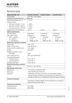
Technical data Safety Mat SM11 with Test principle Switching characteristics at vtest = 250 mm/s Switching operations at 0.1 A Actuation forces Test piece (cylinder) ∅ 11 mm Test piece (cylinder) ∅ 80 mm Test piece (cylinder) ∅ 200 mm Response time with Control Unit ISO 13849-1:2006 MTTFd (Sensor) B10d (Sensor) nop (acceptance) Safety classifications Mechanical operating conditions Sensor size Driving on with industrial trucks Operating temperature individual sensors combined sensors Storage temperature Electrical operating conditions Sensor Maintenance and service Maintenance Joint...
Open the catalog to page 12All Mayser catalogs and technical brochures
-
Public transport
9 Pages
-
Commercial Vehicles
7 Pages
-
Industry Brochure
16 Pages
-
Product catalog
268 Pages
-
Seat occupancy Sensor SBS
4 Pages
-
DIY SE 1 TPE spring contact
4 Pages
-
Safety shoe
4 Pages
-
Consensus with ISO 13849-1
6 Pages
-
RailFR: Sensor, cable
11 Pages
-
Platform screen doors flyer
1 Pages
-
Automotive Brochure
11 Pages
Archived catalogs
-
Ultrasonic sensors brochure
5 Pages
-
Aviation brochure
9 Pages
-
Ultrasonic Industrial Sensor
12 Pages
-
DIY Sensor Profiles
13 Pages
-
Signal Transmission System
3 Pages
-
Control Units
3 Pages
-
Safety Mats SM
20 Pages
-
Miniature Safety Edges
31 Pages
-
Safety Bumper
10 Pages
-
Safety Edges
34 Pages
-
Transmission Systems WLS
3 Pages
-
Safety Bumpers
10 Pages


