- Company
- Products
- Catalogs
- News & Trends
- Exhibitions
Normally closed Safety Edges SL/NCII
1 /20Pages

Normally closed Safety Edges SL/NCII
1 /20Pages
Catalog excerpts

Polymer Electric Product information Normally Closed Safety Edges SL/NC II GmbH & Co. KG Polymer Electric Örlinger Straße 1–3 89073 Ulm GERMANY Tel. +49 731 2061-0 Fax +49 731 2061-222 E-Mail: [email protected] Internet: www.mayser.com
Open the catalog to page 1
Read through the product information carefully. It contains important information on operation, safety and maintenance of the product. Retain the product information for later reference. Always observe the safety instructions on the following pages under ATTENTION. Only use the product for the purpose described in the product information. © Mayser Ulm 2013 2 Normally Closed Safety Edges Important information
Open the catalog to page 2
Definitions See Definitions and Operation Principles in chapter 1 of the Mayser catalogue. Intended use A Safety Edge detects a person or part of the body when pressure is applied to the actuation area. It is a linear tripping device. Its task is to avoid possible hazardous situations for a person within a danger zone, such as shearing and pinching edges. Typical areas of application are door and gate systems, moving parts on machines, platforms and lifting devices. Safe operation of a Safety Edge depends entirely on - the surface condition of the mounting surface, - the correct selection of...
Open the catalog to page 3
Tip For the risk and safety assessment of your machine, we recommend ISO 12100 “Safety of machinery – Basic concepts, general principles for design” . The downstream control must comply with at least ISO 13849-1 category 3 and have inputs for the reliable evaluation of the status of the normally closed Safety Edge. Effective actuation area The parameters X, Y, Z, LNE and the angle α describe the effective actuation area. For the effective actuation area, the following applies: LWB = LSL - 2× LNE Parameters: LWB = Effective actuation length LSL = Overall length of the Safety Edge LNE = Non-sensitive...
Open the catalog to page 4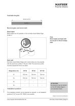
Available lengths 30 cm to 6 m SL/NC II Bend angles and bend radii Bend angles Bend angles are not possible on the normally closed Safety Edge SL/NC II. Note: Bend angles and bend radii are not part of the EC design tests Bend radii Normally closed Safety Edges with a bend radius are only possible with the aluminium profiles C 36 and C 36S. The aluminium profile must be prepared for this at our plant. Installation position ATTENTION No pressure may be exerted on the NC Safety Edge in non-operative mode. The installation position can be selected as required, i.e. all installation positions A to...
Open the catalog to page 5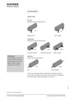
Connection Cable exits 90° exit Distance to front end each 60 mm Standard (S1) S2: 2 cables Lateral exit Distance to front end each 60 mm SL: lateral exit left ATTENTION Axial cable exits (ST1/ST2) must be laid free of tension. A tensile load of max. 50 N apply to cables through cable screw connection. SR: lateral exit right Axial exit without PG-screw connection In the case of several sensors connected in sequence, we recommend version S2, SR2 or ST2. These versions provide an additional line in the rubber profile for feedback to the control. Subject to technical modifications 6 Normally Closed...
Open the catalog to page 6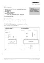
Cable connection ATTENTION It must be ensured that the lines to the downstream control are double insulated • Cable: Ø 3.3 mm PVC, 1× 0.5 mm2; double insulated, short-circuitproof, highly flexible • Cable length: 1.5 m Option: up to max. 200 m • Cable ends: wires stripped Option: Cable ends available with plug and coupling Connection examples Connection example 1 Normally Closed Safety Edge in series with Emergency-Stop button on Emergency-Stop Control Unit. Connecting voltage: DC. Connection example 2 Normally Closed Safety Edge directly connected to control up to PL e as per ISO 13849-1. Connecting...
Open the catalog to page 7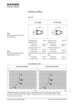
Polymer Electric Test piece (cylinder): 0 80 mm. Rubber profiles Actuation force: Response time Force-distance ratios SL/NC II GP 48 NBR SL/NC II GP 48 EPDM Installation position B, temperature +20 °C, measurement point c3, test piece (cylinder) 0 80 mm A: Actuation distance (200 mm/s), B1/B2/C: total deformation (10 mm/s) at 250 N / 400 N / 600 N_ Subject to technical modifications 8 Normally Closed Safety Edges
Open the catalog to page 8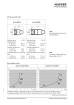
Polymer Electric Actuation force: Response time Actuation force: Response time Test piece (cylinder): 0 80 mm. Force-distance ratios SL/NC II GP 65 EPDM SL/NC II GP 100 EPDM Installation position B, temperature +20 °C, measurement point c3, test piece (cylinder) 0 80 mm A: Actuation distance (200 mm/s), B1/B2/C: total deformation (10 mm/s) at 250 N / 400 N / 600 N_ Subject to technical modifications Normally Closed Safety Edges 9
Open the catalog to page 9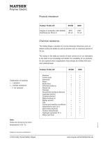
Physical resistance Degree of protection (IEC 60529) Hardness per Shore A Chemical resistance The Safety Edge is resistant to normal chemical influences such as diluted acids and alkalis as well as alcohol over an exposure period of 24 hrs. The values in the table are results of tests carried out in our laboratory to the best of our knowledge and belief. The suitability of our products for your special area of application must always be verified with your own practical tests. Rubber Profile GP Explanation of symbols: + = resistant ± = limited resistance - = not resistant Acetone Formic acid Ammonia...
Open the catalog to page 10
Fixing rails Normally closed Safety Edges SL/NC II are mounted directly to the dangerous main and secondary closing edges. The C26 and C 36 ranges of aluminium profiles are used for mounting. The aluminium profiles are mounted with M5 screws or rivets. Material properties • AlMgSi0.5 F22 • Wall thickness 2 mm • Tolerances as per EN 755-9 Two-part profile for GP 48: For convenient assembly and disassembly. The rubber profile is clipped into the upper section and the upper section inserted in the installed lower section and fastened. Subject to technical modifications Normally Closed Safety Edges...
Open the catalog to page 11
Standard profile for GP 48: The aluminium profile must first be installed on the closing edge and the rubber profile can than be clipped into the aluminium profile. Two-part profile for GP 65 and GP 100: For convenient assembly and disassembly. The rubber profile is clipped into the upper section and the upper section inserted in the installed lower section and fastened. Subject to technical modifications 12 Normally Closed Safety Edges
Open the catalog to page 12All Mayser catalogs and technical brochures
 Public transport
9 Pages
 Commercial Vehicles
7 Pages
 Industry Brochure
16 Pages
 Product catalog
268 Pages
 Seat occupancy Sensor SBS
4 Pages
 DIY SE 1 TPE spring contact
4 Pages
 Safety shoe
4 Pages
 Consensus with ISO 13849-1
6 Pages
 RailFR: Sensor, cable
11 Pages
 Automotive Brochure
11 Pages


Archived catalogs
 Aviation brochure
9 Pages
 Ultrasonic sensors brochure
5 Pages
 Signal Transmission System
3 Pages
 DIY Sensor Profiles
13 Pages
 Safety Mats SM
20 Pages
 Safety Mat SM11
13 Pages
 Control Units
3 Pages
 Miniature Safety Edges
31 Pages
 Safety Bumper
10 Pages
 Safety Edges
34 Pages
 Ultrasonic Industrial Sensor
12 Pages
 Safety Bumpers
10 Pages
 Transmission Systems WLS
3 Pages