- Catalogs
- MAXDRILL ROCK TOOLS CO., LTD
- Concentric
Concentric
1 /6Pages

Concentric
1 /6Pages
Catalog excerpts

Concentric Casing Systems Application Range: It is recommended to drill in rock formation where contains some ovals and fractures. Design Principles: The stable and reliable working performance and the less vibration of drill rig. Different Structures: Concentric system with ring bits, wing and blocks. A: Discharge Head B: Drill Rod C: Guide Sleeve D: DTH Hammer E: Casing Tube F: Pilot Bit G: Casing Shoe H: R
Open the catalog to page 1
With Ring Bits 1. When drilling starts, the pilot bit drive the ring bit down to the hole, followed the casing shoe and casing tube. 2.At the bedrock, start Reverse circulation of tools and pull the pilot bit from the drill hole leaving the ring bit in the hole. 3. Pour the concrete or do the next constructions work. 1.After the drilling starts, the pilot bit drive the ring bit down to the hole, followed the casing shoe and casing tube. 2. At the bedrock, start Reverse 3. Pull the casing tube out with the circulation of tools and pull the pilot ring bit and at the same time pour the...
Open the catalog to page 2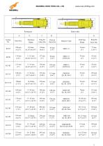
Thickness Range Hammer Type Drill Pipe Range
Open the catalog to page 3
With Wings Guide Device Operation Procedure 1. The wings swing out soon after the drilling start and the ream drives the casing shoes and tubes in the drill hole. 2. After completed the drilling process in overburden rock formation, as soon as the reverse drilling process start the wings will get closed, so the drilling tools can be pull back from the drill hole. 3. Follow the next drilling process. Thickness Range Hammer Type Drill Pipes
Open the catalog to page 5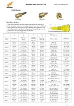
MAXDRILL R M ROCK TOOLS S CO., LTD www.max x‐drilling.com m Operation Procedure O 1. At the start of drilling, th blocks slid down thro he des ough the groo oves on nd rives the casi shoes and tubes into th drill hole. ing d he pilot bit, an the ream dr 2. 2 After comp plete the drilli process in overburden rock formations, raise ing n the drilling tools then the blocks will get closed th hrough the gro ooves, the led the drilling tools can be pull out from t drill hole. 3. 3 Next constr ruction can be followed. e A Thickness Range Pilot bit t with B Block Outer...
Open the catalog to page 6All MAXDRILL ROCK TOOLS CO., LTD catalogs and technical brochures
 SELF-DRILLING ANCHOR SYSTEM
13 Pages
 TAPHOLE DRILL BIT
4 Pages
 TAPHOLE DRILL ROD
5 Pages
 Y20 HAND-HELD ROCK DRILL
2 Pages
 YT28 JACKLEG DRILL
2 Pages
 BREAKER STEEL
1 Page
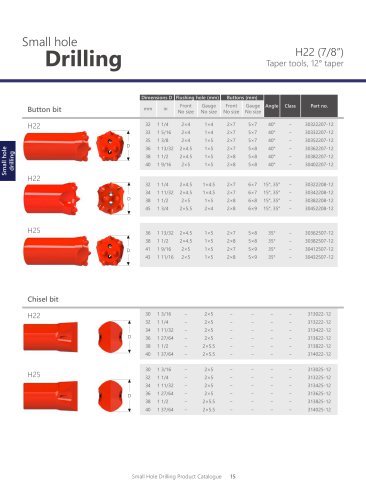
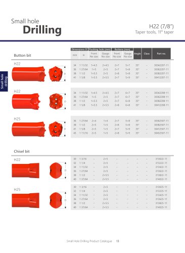
 12° TAPERED DRILLING TOOLS
6 Pages
 DOWN THE HOLE BIT
4 Pages
 6° TAPERED DRILLING TOOLS
6 Pages
 7° TAPERED DRILLING TOOLS
5 Pages
 DTH HAMMER
74 Pages
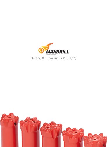
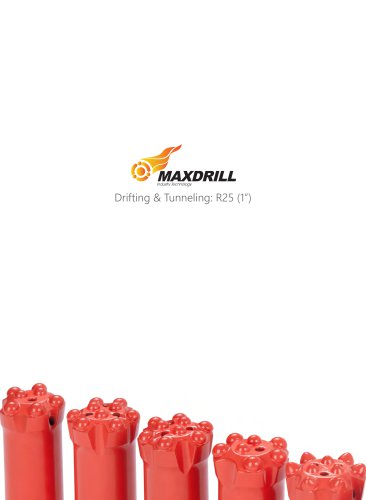
 Drifting & tunneling
20 Pages
 TopHammer-drilling-tools
63 Pages
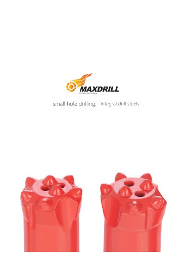
 integral drill steel
1 Page
 6° taper drill rod and bit
2 Pages
 12 inch DTH hammer and bit
20 Pages
 10 inch DTH hammer and bit
19 Pages
 8 inch DTH hammer and bit
22 Pages
 5 inch DTH hammer and bit
23 Pages
 3 inch DTH hammer and bit
17 Pages
 Down the hole drill bit--QL60
22 Pages
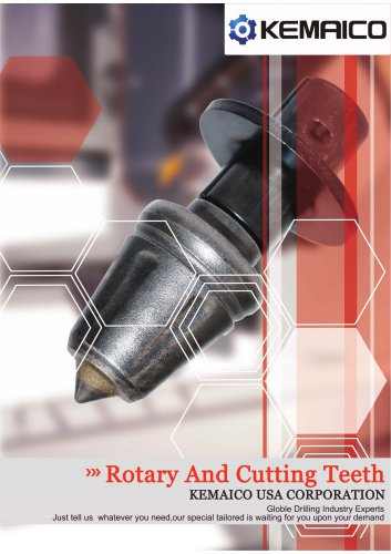 Rotary and cutting teeth
5 Pages
 Wear parts
9 Pages
 Engineering Cutter Tools
13 Pages
 Y24 Hand-Held Rock Drill
2 Pages
 Maxdrill Break steel
1 Page
 Maxdrill Hand splitter
2 Pages
 Maxdrill Plug Hole Rod
1 Page
 Maxdrill Rock Drills Y28
3 Pages
 Maxdrill Rock Drills Y24
3 Pages
 Maxdrill Rock Drills Y20
3 Pages
 Maxdrill DTH drill pipes
4 Pages
 Maxdrill Down The Hole Hammer
54 Pages
 DTH Drill Pipes
4 Pages
 Integral Drill Rod
5 Pages


- Grinding machine
- Drilling tool
- Solid drill bit
- Multi-purpose drilling tool
- Tungsten carbide drill bit
- Threaded adapter
- Drill attachment
- Straight adapter
- Oil & gas drill bit with buttons
- Anchor bolt
- Down-the-hole hammer
- Rock splitter
- Rock button bit
- Tunneling oil & gas drill bit
- Drifting oil & gas drill bit
- Drill pipe adapter
- Tophammer button bit
- Bench drilling button bit
- Production oil & gas drill bit