- Company
- Products
- Catalogs
- News & Trends
- Exhibitions
AIR COMPRESSORS
1 /16Pages

AIR COMPRESSORS
1 /16Pages
Catalog excerpts

ma±±BiAIR COMPRESSORS THE REAL ECONOMIC AND ENVIRONMENTAL IMPACT OF USING THE CURRENT INDUSTRY STANDARD LIFE CYCLE COST ANALYSIS
Open the catalog to page 1
ABSTRACT Today’s commonly accepted method of calculating Life Cycle Cost (LCC) for industrial Air Compressors is challenged due to the fact that assuming constant compressor efficiencies through the life of the compressor is incorrect. It is shown how, in a screw compressor, very small interlobe and axial clearance difference results in important performance losses and how these changes are well within the acceptable wear of the bearings used in the same compressors. It is also shown how in the Mattei Rotary Vane Compressor, there is a short running-in period, lasting roughly 1000 hrs, in which...
Open the catalog to page 2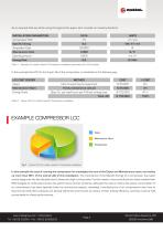
As an example that we will be using throughout this paper, let's consider an industry standard: In this example the LCC for the 5-year life of the compressor is calculated in the following way: LCC COST CENTER Capex Maintenance @5yrs Energy Costs Table 2 - Typical LCC of a medium sized Air Compressor installation Energy Costs In this example the cost of running the compressor far outweighs the sum of the Capex and Maintenance costs, and makes up more than 90% of the overall LCC of this installation. The importance of the Specific Energy of a compressor has taken centre stage over the last decades...
Open the catalog to page 3
AIR COMPRESSORS AND GLOBAL WARMING Today, it is a widely accepted fact that global warming is currently the greatest threat to our Planet and the continued existence of Humanity. One independent study performed by the Intergovernmental Panel on Climate Change confirms that at the present greenhouse gas emission rate, a warming exceeding 4°C of the average global temperature by the end of the century is going to be unavoidable [1]. To the layman, this may not sound like much, until one considers that experts unanimously agree that a 2°C temperature increase is the limit to avoid irreversible damage...
Open the catalog to page 4
TYPICAL COMPRESSOR LIFE CYCLE COST EVALUATION Currently a potential client, who is interested in buying an industrial air compressor, will typically ask the manufacturer for the compressor's technical data sheet to estimate the Life Cycle Cost of his investment over the next 5-10 year period. In the USA, the Compressed Air and Gases Institute (CAGI) has set up a consumer friendly portal from which one can download technical data sheets regarding air compressors of various global manufacturers. Any data published on the CAGI website has been independently verified and approved by a third party...
Open the catalog to page 5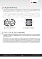
SCREW COMPRESSOR To understand why the above assumption does not apply to screw compressors one has to examine the engineering principle. Rotary screw compressor design consists of a pair of meshing helical lobed rotors. The rotor shafts are supported by roller and thrust bearings and generally one rotor drives the other by means of the helical profiles. During rotation the screw profiles uncover an intake orifice at one end of the stator, through which the air enters and fills the volume between the profiles. On the opposite side the profiles penetrate each other, thereby reducing the volume,...
Open the catalog to page 6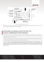
Fig. 5 – Leakage pathways in a screw compressor Therefore, since the performance of screw compressors is highly affected by leakage, any modifications of the clearances within them must have an important effect on their efficiency [6]. INTERLOBE CLEARANCE AND ITS EFFECT ON SCREW COMPRESSOR PERFORMANCE Today modern rotor machining centres have been shown to maintain extreme tolerances of up to 3µm. This means that, as far as rotor production alone is concerned, clearances between the rotors can be as small as 12µ [7] (as a frame of reference the average width of a human hair is 70µm). Although...
Open the catalog to page 7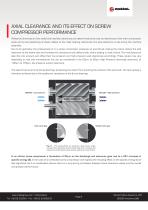
AXIAL CLEARANCE AND ITS EFFECT ON SCREW COMPRESSOR PERFORMANCE Whilst the dimensions of the radial and interlobe clearances are determined by the size and tolerances of the main compressor parts and by the positioning of these relative to the roller bearing clearances, the axial clearance is set during the machine assembly. Due to its geometry, the pressurised air in a screw compressor produces an axial thrust making the rotors reduce the side clearance at the intake side and increase the clearance at the delivery side, where sealing is most critical. The manufacturers take this into account...
Open the catalog to page 8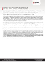
SCREW COMPRESSOR AT ZERO HOUR Off the manufacturing assembly line the Screw compressor interlobe and axial clearances will be precise and within the manufacturers guidelines to allow the specified compressor performance: this is clear from the fact that, at Zero Hours, there are a few major Screw compressor manufacturers whose CAGI-verified data is among the best on the market. But what happens to these important clearances when the Screw Compressor starts running? It is a well-known fact that both roller bearings and thrust bearings are subject to wear, and their wear rate is subject to both...
Open the catalog to page 9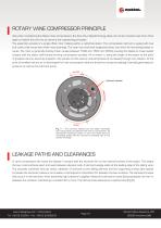
ROTARY VANE COMPRESSOR PRINCIPLE Also when considering the Rotary Vane compressors, the Zero Hour Specific Energy does not remain constant over time. Once again to explain this one has to examine the engineering principles. The assembly consists of a single offset rotor rotating within a cylindrical stator. The compression element is sealed with two end covers that house two white metal bushings. The rotor has machined longitudinal slots, into which fit free sliding blades or vanes. The rotor is generally directly driven usually between 1000 and 1500 rpm (50Hz) causing the blades to make sealed...
Open the catalog to page 10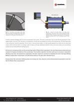
Fig. 8 – The vanes move freely in the rotor slots and always seal against the stator wall. Performance does not deteriorate even after many tens of thousands of operating hours Fig. 9 – There is no axial thrust in a rotary vane compressor. The rotor is free to move axially and is kept equally spaced from the end covers by means of the lubricant, which is injected under pressure. The injected lubricant prevents the air from escaping along the side planes Another potential leakage path is via the compressor end covers. The vane compressor has no axial thrust pushing the rotor against either end...
Open the catalog to page 11All MATTEI catalogs and technical brochures
 RVD 30÷55 i
8 Pages
 RVD 30÷55
8 Pages
 RVX Series
8 Pages
 RVX 45-55-75 Ultra Performance
12 Pages
 GAS APPLICATIONS
12 Pages
 OEM
OEM12 Pages
 ENERGY SAVING
24 Pages
 AIR TREATMENT
20 Pages
 AIR CENTRE SERIES
16 Pages
 ERC
ERC6 Pages
 RAILWAY APPLICATIONS
12 Pages
 AIR CENTRE 110 - 132 kW
6 Pages
 HIGH-EFFICIENCY SERIES
8 Pages
 Compressors
4 Pages
 VARIABLE SPEED SERIES
8 Pages
 RVXi 55-75-90 Series
12 Pages
 CONTROL SYSTEMS
8 Pages
 AIR CENTRE 30 - 45 kW
6 Pages
 CONCERTO System
8 Pages
 CLASSIC SERIES
16 Pages
 BLADE Series
8 Pages
 BLADE 4 - 5 - 7 - 11
8 Pages
 BLADE i 8 - 12
8 Pages
 BLADE 15 - 18 - 22
8 Pages
 BLADE i 15 - 18 - 22
8 Pages
 BLADE 1-2-3
8 Pages
 Blade 1-3
8 Pages
 Air treatment
20 Pages
 FM
FM6 Pages
 Maxima series
8 Pages
 Series MBL
8 Pages
 CONDENSATE TREATMENT
2 Pages
 OIL-WATER SEPARATORS
8 Pages
 Blowers SERIES SM - SMR - SMT
16 Pages


Archived catalogs
 Classic series 1,5-3kW
6 Pages
 AC 55-75-9O
8 Pages
- Vessel
- Positive-displacement compressor
- Stationary compressor
- Liquid filter
- Industrial compressor
- Storage vessel
- Filter with cartridge
- Solids separator
- Lubricated compressor
- Oil-free compressor
- Industrial use filter
- Compact compressor
- Centrifugal classifier
- Mobile compressor
- Liquids separator
- Vertical tank
- Low-noise compressor
- Cooled compressor