
Catalog excerpts
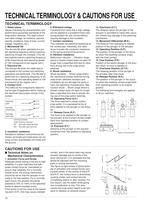
The position of the plunger or the actua-tor when the traveling contacts snaps with the fixed contact. Position of the switch plunger or the actu- ator when no force is applied to. 17. Overtravel Position (O.T.P.) The position of the plunger or the actua-tor when the traveling contact snaps back from operating position to its original position. The following terminologies are applied to all our switches. 15. Operating Position (O.P.) 16. Free Position (F.P.) The stopping position of the plunger or the actuator after total travel. 18. Release Position (R.P.) 14. Movement Differential (M.D.) 13. Overtravel (O.T.) The distance from operating to release position of the plunger or the actuator. The distance which the plunger or the actuator is permitted to travel after actua- tion without any damage to the switching mechanism. 11. Release Force (R.F.) Distance of the plunger or the actuator movement from free position to operating position. 10. Operating Force (O.F.) The force to be applied to the plunger or the actuator at the moment contact snaps back from operated position to unoper-ated position. 12. Pretravel (P.T.) The force required to cause contact snap-action. It is expressed terms of force applied to the plunger or the actua- tor. 9. Shock resistance Malfunction vibration ... Vibration range where a closed contact does not open for longer than a specified time due to vibra- tions during use of the snap-action switches. Shock durability ... Shock range where the mechanical shocks received during snap-action switches transport and installation do not damage the parts or harm the operating characteristics. Mal- function shock ... Shock range where a closed contact does not open for longer than a specified time due to shocks dur- ing use of the snap-action switches. 8. Vibration resistance 7. Contact resistance 6. Withstand voltage This indicates the electrical resistance at the contact part. Generally, this resis- tance includes the conductor resistance of the spring and terminal portions. Threshold limit value that a high voltage can be applied to a predetermined mea- suring location for one minute without causing damage to the insulation. > This refers to the components determin-ing the type of application which make up the electrical input/output circuits in the contact. The service life when the rated load is connected to the contact and switching operations are performed. (The life test is performed at a switching frequency of 20 times/minute and operating speed of 100 mm/second at the regular cam.) 1. Rated values 3. Electrical life Values indicating the characteristics and performance guarantee standards of the snap-action switches. The rated current and rated voltage, for instance, assume specific conditions (type of load, current, voltage, frequency, etc.). 2. Mechanical life The service life when operated at a pre- set operating frequency without passing electricity through the contacts. (The life test is performed at a switching frequency of 60 times/minute and operating speed of 100 mm/second at the regular cam.) 5. Insulation resistance Resistance between noncontinuous ter-minals, terminals and metal parts not car-rying current, and between terminals and the ground. > SwitchingtypeNormallyclosed typeNormallyopen type COMNCNCNONOCOMCOM F.P.O.F.R.F.T.T.M.D.O.T.T T.P.O.P.P.T.T.F.R.P. Terminal symbolsCOM:NC: NO: Common terminalNormally closed terminalNormally open terminal Center of mounting holes OFRFPTNCOn FPOn reversalOn reversalOn OTPNOStroke StrokeMDOT 1. Actuation Force and Stroke Adequate stroke setting is the key to high reliability. It is also important that ade-quate contact force be maintained to ensure high reliability. For a normally closed circuit, the driving mechanism should be set so that the actuator is nor-mally in the free position. For a normally open circuit, the actuator should be pressed to 70% to 100% of the speciү́ed stroke to absorb possible errors. If the stroke is set too close to the operat-ing point (O.P.), this may cause unstable contact, and in the worst case may cause actuator damage due to inertia of the drive mechanism. It is advisable that the stroke be adjusted with the mounting plate or driving mechanism. The figure at right shows a typical exam- ple of activation and contact forces vary-ing with stroke. In the vicinity of the O.P. and R.P., the contact force is diminished, causing chatter and contact bounce immediately before or after reversal. For this reason, use the switch while giving due consideration to this. This also causes the snap action switch to be sen- sitive to vibration or physical impact. > FP RP OP TTP Contact forceOperating force 10 >
Open the catalog to page 1
4. Driving Mechanism Use of a driving mechanism which will cause physical impact to the actuator should be avoided. 7. To prevent contact fusion failure, be sure to use a serial resistance for each capacitive load. 8. If snap action switch operation is syn-chronized with the AC supply phase, this may cause: shortened electrical life, con-tact fusion failure, contact transfer, or other reliability problems. 6. Ratings are measured under the fol-lowing conditions: Inductive load: Power factor = 0.6 to 0.7 Time constant = 7 ms or less (DC) 3. Mechanical Conditions for Type Selection Actuator...
Open the catalog to page 2All Matsushita Electric Works catalogs and technical brochures
-
 Narrow pitch RF connectors
12 Pages
-
 High Current Connectors
12 Pages
-
 Ultra-slim Photoelectric Sensor
16 Pages
-
 Laser Distance Sensor
16 Pages
-
 CA RELAYS
8 Pages
-
 AQ-J RELAYS
19 Pages
-
 AQ-H RELAYS
14 Pages
-
 AQ-G RELAYS
14 Pages
-
 AQ-A RELAYS (DC output type)
15 Pages
-
 AQ-A RELAYS (AC output type)
17 Pages
-
 AQ8 RELAYS
17 Pages
-
 AQ1 RELAYS
16 Pages
-
 HG-S series
18 Pages
-
 HE
HE6 Pages
-
 SFD-WL3
2 Pages
-
 SF4D
SF4D42 Pages
-
 ELC500
8 Pages
-
 AC Fan Motor 80×38t
1 Pages
-
 GT707
GT7072 Pages
-
 GT SERIES
24 Pages
-
 GT32-R
2 Pages
-
 Shin-G Series
293 Pages
-
 MINAS-BL KV Series
52 Pages
-
 LP-GS series
12 Pages
-
 LP- V SERIES, LP- W SERIES
16 Pages
-
 LP-M
LP-M12 Pages
-
 ER-VW
ER-VW8 Pages
-
 ER-TF SERIES
6 Pages
-
 ER-X001
4 Pages
-
 EWA2
EWA28 Pages
-
 RJ RELAYS (ARJ)
5 Pages
-
 SF Relays
4 Pages
-
 mechDE Relays (ADE)
4 Pages
-
 EX-L200
12 Pages
-
 gtseries_e_cata
24 Pages
-
 ce_up50_1
6 Pages
-
 digest_e_cata
32 Pages
-
 fx-100
20 Pages
-
 uj30
uj3012 Pages
-
 Power relay selector chart
8 Pages
-
 NEW & KEY PRODUCTS 2012
32 Pages
-
 Aicure UJ30/35 Catalog
12 Pages
-
 KW2G-H
4 Pages
-
 LP-S series
12 Pages
-
 LP-S500W
12 Pages
-
 SC-GU3
8 Pages
-
 SL-PK01
2 Pages
-
 DPC-L100/DPH-L100
12 Pages
-
 FP-X0
FP-X08 Pages
-
 FPOR
FPOR20 Pages
-
 PM 2
PM 26 Pages
-
 PM-24
PM-246 Pages
-
 LP-Z Series
4 Pages
-
 LP-V/W Series
16 Pages
-
 FP2SH
FP2SH24 Pages
-
 LP-300 Series
12 Pages
-
 SF4B Ver.2
48 Pages
-
 SL-VGU1-485
2 Pages
-
 PM-44/PM-54
10 Pages
-
 PV200
PV20022 Pages
-
 FX-500
20 Pages
-
 Flat Type Fiber
2 Pages
-
 LP-400 Series
16 Pages
-
 MIPTEC catalog
8 Pages
-
 PM-64
PM-648 Pages


![AFP7MW [Multi-wire link unit]](https://img.directindustry.com/pdf/repository_di/15605/afp7mw-multi-wire-link-unit-771067_1mg.jpg)


Archived catalogs
-
 Lighting Control Catalog
42 Pages
-
 Time Switches
2 Pages
-
 Time & Synchronization VIC100
1 Pages
-
 GPS Products Antennas
2 Pages
-
 Phototriac Coupler
4 Pages
-
 Signal Relays
31 Pages