Group: Matsushita Electric Works

Catalog excerpts

High Current Connectors [For board-to-FPC] R35 ( 0.35 mm pitch ) Product Catalog
Open the catalog to page 1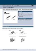
High Current Connectors【For board-to-FPC】 Supports 5 A for power terminal The ultra-small ( width 1.7mm ) high mating force connector FEATURES ● Supports 5 A power terminals ● Slim: width 1.7 mm ● Low profile construction: mated height 0.6 mm ● Robust construction with metal exposure of flange section TYPICAL APPLICATIONS 1.7 mm ● Wearable devices, smartphones, hearable devices and other small mobile devices DETAILS FEATURES ■ Achieves high robustness with exposed metal structure on flange part Compact size ( width = 1.7 mm, mated height = 0.6 mm ) and capable of 5 A current Socket 4.20 mm (...
Open the catalog to page 2
High Current Connectors R35 ( 0.35 mm pitch ) ORDERING INFORMATION ( PART NO. ) (2 digits) 10:10 pins 16:16 pins 20:20 pins 24:24 pins 26:26 pins 30:30 pins 40:40 pins 50:50 pins 60:60 pins Mated height PRODUCT TYPES Part No. Standard packing Mated height Outer carton Notes) 1: Order unit: For volume production: 1-inner carton ( 1-reel ) units. For samples, please contact our sales representative. 2: Please contact our sales representative for connectors having a number of pins other than those listed above. Panasonic Industry Co., Ltd. Electromechanical Control Business Division...
Open the catalog to page 3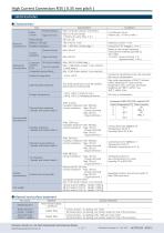
Panasonic Industry Co., Ltd. Electromechanical Control Business Division industrial.panasonic.com/ac/e/ 3
Open the catalog to page 4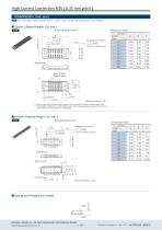
|caDThe CAD data of the products with a " CAD " mark can be downloaded from our Website. Dimension table Dimensions Number of pins Dimension table The degree of terminal flat (Contact and Power terminal) Dimensions Number of pins ■ Socket and Header are mated o header +1 ..d-! Panasonic Industry Co., Ltd. Electromechanical Control Business Division industrial.panasonic.com/ac/e/ 4
Open the catalog to page 5
In accordance with JIS C 0806-3:1999. However, not applied In accordance with EIAJ ET-7200B to the mounting-hole pitch of some connectors ■ Dimension table Type / Mated height Panasonic Industry Co., Ltd. Electromechanical Control Business Division industrial.panasonic.com/ac/e/ 5
Open the catalog to page 6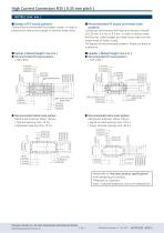
High Current Connectors R35 ( 0.35 mm pitch ) NOTES ( Unit: mm ) ■ Design of PC board patterns Conduct the recommended foot pattern design, in order to preserve the mechanical strength of terminal solder areas. ■ Recommended PC board and metal mask patterns Connectors are mounted with high pitch density, intervals of 0.35 mm, 0.4 mm or 0.5 mm. In order to reduce solder and flux rise, solder bridges and other issues make sure the proper levels of solder is used. The figures are recommended patterns. Please use them as a reference. ■ Socket ( Mated height: 0.6 mm ) ■ Header ( Mated height: 0.6...
Open the catalog to page 7
Notes on Using Narrow pitch RF Connectors/Narrow pitch Connectors/High Current Connectors About safety remarks Observe the following safety remarks to prevent accidents and injuries. • Do not use these connectors beyond the specification sheets. The usage outside of specified rated current, dielectric strength, and environmental conditions and so on may cause circuitry damage via abnormal heating, smoke, and fire. • In order to avoid accidents, your thorough specification review is appreciated. Please contact our sales representative if your usage is out of the specifications. Otherwise,...
Open the catalog to page 8
Notes on Using Narrow pitch RF Connectors/Narrow pitch Connectors/High Current Connectors Regarding the selection of the connector placement machine and the mounting procedures • Select the placement machine taking into consideration the connector height, required positioning accuracy, and packaging conditions. • Be aware that if the chucking force of the placement machine is too great, it may deform the shape of the connector body or connector terminals. • Be aware that during mounting, external forces may be applied to the connector contact surfaces and terminals and cause deformations. •...
Open the catalog to page 9
■ Hand soldering • Set the soldering iron so that the tip temperature is less than that given in the table below. Table A • Do not allow flux to spread onto the connector leads or PC board. This may lead to flux rising up to the connector inside. • Touch the soldering iron to the foot pattern. After the foot pattern and connector terminal are heated, apply the solder wire so it melts at the end of the connector terminals. Be aware that soldering while applying a load on the connector terminals may cause improper operation of the connector. Thoroughly clean the soldering iron. Flux from the...
Open the catalog to page 10
Notes on Using Narrow pitch RF Connectors/Narrow pitch Connectors/High Current Connectors Handling the PC board ■ Handling the PC board after mounting the connector The soldered areas should not be subjected to force. When cutting or bending the PC board after mounting the connector, be careful that the soldered sections are subjected to excessive force. Storage of connectors • To prevent problems from voids or air pockets due to heat of reflow soldering, avoid storing the connectors in areas of high humidity. • Depending on the connector type, the color of the connector may vary from...
Open the catalog to page 11
Panasonic INDUSTRY Panasonic Industry Co.f Ltd. Electromechanical Control Business Division ■ 1006, Oaza Kadoma, Kadoma-shi, Osaka 571-8506, Japan industrial.panasonic.com/ac/e/ Specifications are subject to change without notice. ACCTB125E 202312
Open the catalog to page 12All Matsushita Electric Works catalogs and technical brochures
-
 Narrow pitch RF connectors
12 Pages
-
 Ultra-slim Photoelectric Sensor
16 Pages
-
 Laser Distance Sensor
16 Pages
-
 CA RELAYS
8 Pages
-
 AQ-J RELAYS
19 Pages
-
 AQ-H RELAYS
14 Pages
-
 AQ-G RELAYS
14 Pages
-
 AQ-A RELAYS (DC output type)
15 Pages
-
 AQ-A RELAYS (AC output type)
17 Pages
-
 AQ8 RELAYS
17 Pages
-
 AQ1 RELAYS
16 Pages
-
 HG-S series
18 Pages
-
 HE
HE6 Pages
-
 SFD-WL3
2 Pages
-
 SF4D
SF4D42 Pages
-
 ELC500
8 Pages
-
 AC Fan Motor 80×38t
1 Pages
-
 GT707
GT7072 Pages
-
 GT SERIES
24 Pages
-
 GT32-R
2 Pages
-
 Shin-G Series
293 Pages
-
 MINAS-BL KV Series
52 Pages
-
 LP-GS series
12 Pages
-
 LP- V SERIES, LP- W SERIES
16 Pages
-
 LP-M
LP-M12 Pages
-
 ER-VW
ER-VW8 Pages
-
 ER-TF SERIES
6 Pages
-
 ER-X001
4 Pages
-
 EWA2
EWA28 Pages
-
 RJ RELAYS (ARJ)
5 Pages
-
 SF Relays
4 Pages
-
 mechDE Relays (ADE)
4 Pages
-
 EX-L200
12 Pages
-
 gtseries_e_cata
24 Pages
-
 ce_up50_1
6 Pages
-
 digest_e_cata
32 Pages
-
 fx-100
20 Pages
-
 uj30
uj3012 Pages
-
 Power relay selector chart
8 Pages
-
 NEW & KEY PRODUCTS 2012
32 Pages
-
 Aicure UJ30/35 Catalog
12 Pages
-
 KW2G-H
4 Pages
-
 LP-S series
12 Pages
-
 LP-S500W
12 Pages
-
 SC-GU3
8 Pages
-
 SL-PK01
2 Pages
-
 DPC-L100/DPH-L100
12 Pages
-
 FP-X0
FP-X08 Pages
-
 FPOR
FPOR20 Pages
-
 PM 2
PM 26 Pages
-
 PM-24
PM-246 Pages
-
 LP-Z Series
4 Pages
-
 LP-V/W Series
16 Pages
-
 FP2SH
FP2SH24 Pages
-
 LP-300 Series
12 Pages
-
 SF4B Ver.2
48 Pages
-
 SL-VGU1-485
2 Pages
-
 PM-44/PM-54
10 Pages
-
 PV200
PV20022 Pages
-
 FX-500
20 Pages
-
 Flat Type Fiber
2 Pages
-
 LP-400 Series
16 Pages
-
 MIPTEC catalog
8 Pages
-
 PM-64
PM-648 Pages


![AFP7MW [Multi-wire link unit]](https://img.directindustry.com/pdf/repository_di/15605/afp7mw-multi-wire-link-unit-771067_1mg.jpg)


Archived catalogs
-
 Lighting Control Catalog
42 Pages
-
 Time Switches
2 Pages
-
 Time & Synchronization VIC100
1 Pages
-
 GPS Products Antennas
2 Pages
-
 Phototriac Coupler
4 Pages
-
 Signal Relays
31 Pages
