
Catalog excerpts
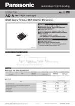
Automation Controls Catalog Solid State Relays AQ-A RELAYS (DC output type) Small Screw Terminal SSR Ideal for DC Control us • Compact size: W 40 x L 58 x H 25.5 mm • With terminal cover for safety (output side only) Note: Cover on input side available as option. • Mounting pitch: 47.5 mm • Internal diode protects element on output side • With LED indication for operation status verification • Safety standards • C-UL (UL508, UL60950-1) certified • VDE (EN60950-1) reinforced insulation certified TYPICAL APPLICATIONS • Storage battery system • Photovoltaic power generation system • For control of all types of business equipment and industrial use DC heaters/motors, etc. ORDERING INFORMATION (PART NO.) * When the load voltage is AC type, please refer to “AQ-A RELAYS (AC only)”. ■ AQ-ASolid State Relays (DC output type)
Open the catalog to page 1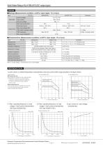
■ Ratings (Measurement condition: at 20°C, Input ripple: 1% or less) Panasonic Corporation Electromechanical Control Business Division industrial.panasonic.com/ac/e/ 2
Open the catalog to page 2
Solid State Relays AQ-A RELAYS (DC output type) Unit: mm CAD The CAD data of the products with a “CAD” mark can be downloaded from our Website. Mounting hole pattern Slim heat sink (AQP812) Mounting hole pattern External dimensions (Effective screw depth: 6 mm) “A” part Note: When using on a DIN rail, please install so that the “A” part is on top. Panasonic Corporation Electromechanical Control Business Division industrial.panasonic.com/ac/e/
Open the catalog to page 3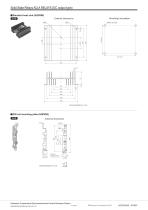
Solid State Relays AQ-A RELAYS (DC output type) Standard heat sink (AQP808) Mounting hole pattern External dimensions DIN rail mounting plate (AQP809) CAD Panasonic Corporation Electromechanical Control Business Division industrial.panasonic.com/ac/e/
Open the catalog to page 4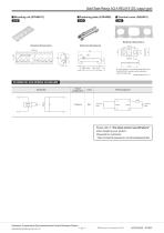
Solid State Relays AQ-A RELAYS (DC output type) Solid State Relays AQ-A RELAYS (DC output type) ■ Fastening plate (ATA4806) ^Terminal cover (AQA801) CAD CAD External dimensions SCHEMATIC AND WIRING DIAGRAMS Schematic Output configuration Wiring diagram Please refer to "the latest product specifications" when designing your product. •Requests to customers: https://industrial.panasonic.com/ac/e/salespolicies/ Panasonic Corporation Electromechanical Control Business Division industrial.panasonic.com/ac/e/ 5
Open the catalog to page 5
Control voltage - -source T SAFETY WARNINGS • Do not use the product under conditions that exceed the range of its specifications. It may cause overheating, smoke, or fire. • Do not touch the recharging unit while the power is on. There is a danger of electrical shock. Be sure to turn off the power when performing mounting, maintenance, or repair operations on the relay (including connecting parts such as the terminal socket and socket). 1. Derating design Derating is a significant factor for reliable design and product life. Even if the conditions of use (temperature, current, voltage,...
Open the catalog to page 6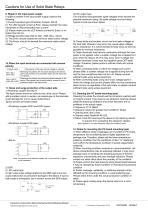
Load power supply 9. Ripple in the input power supply If ripple is present in the input power supply, observe the following: 1) Current-sensitive type (Phototriac Coupler, AQ-H) (1) For LED forward current at Emin, please maintain the value mentioned at “Recommended input current.” (2) Please make sure the LED forward current for Emax. is no higher than 50 mA. 2) Voltage-sensitive type (AQ-G, AQ1, AQ8, AQ-J, AQ-A) (1) The Emin. should exceed the minimum rated control voltage (2) The Emax. should not exceed the maximum rated control voltage 10. When the input terminals are connected with...
Open the catalog to page 7
Cautions for Use of Solid State Relays Cautions for Use of Solid State Relays 14. Soldering 1) When soldering surface-mount terminals, the following conditions are recommended. (1) IR (Infrared reflow) soldering method (Recommended condition reflow: Max. 2 times, measurement point: soldering lead) (2) Other soldering methods Other soldering methods (VPS, hot-air, hot plate, laser heating, pulse heater, etc.) affect the relay characteristics differently, please evaluate the device under the actual usage. (3) Soldering iron method Tip temperature: 350 to 400°C 662 to 752°F Wattage: 30 to 60 W...
Open the catalog to page 8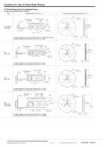
Cautions for Use of Solid State Relays 18. The following shows the packaging format 1) Tape and reel (Phototriac coupler) Type Tape dimensions (Unit: mm inch) Dimensions of paper tape reel (Unit: mm inch) 21±0.8 .827±.031 Tractor feed holes 1.55±0.05 dia. .061±.002 dia. Device mounted on tape 2.8±0.3 .110±.012 ±0.1 (1) When picked from 1/2-pin side: Part No. APT❍❍❍❍SX (Shown above) (2) When picked from 3/4-pin side: Part No. APT❍❍❍❍SZ Tractor feed holes 1.5 ±0.1 dia. −0 .059±.004 dia. −0 Device mounted on tape 12±0.1 .472±.004 (1) When picked from 1/2-pin side: Part No. APT❍❍❍❍AX (2) When...
Open the catalog to page 9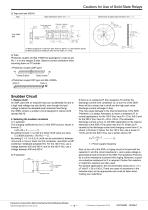
Cautions for Use of Solid State Relays 2) Tape and reel (AQ-H) Type Tape dimensions (Unit: mm inch) Dimensions of paper tape reel (Unit: mm inch) 21±0.8 .827±.031 80±1 dia. 3.150±.039 dia. Device mounted on tape 12±0.1 .472±.004 (1) When picked from 1/2/3/4-pin side: Part No. AQH❍❍❍❍AX (Shown above) (2) When picked from 5/6/8-pin side: Part No. AQH❍❍❍❍AZ 3) Tube Phototriac coupler and AQ-H SSR are packaged in a tube as pin No. 1 is on the stopper B side. Observe correct orientation when mounting them on PC boards. Snubber Circuit 1. Reduce dv/dt An SSR used with an inductive load can...
Open the catalog to page 10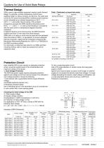
Thermal Design SSRs used in high-reliability equipment require careful thermal design. In particular, junction temperature control has a significant effect on device function and life time. The rated load current for PC board-mounting SSRs is defined as the maximum current allowable at an ambient temperature of 40°C 104°F (30°C 86°F) and under natural cooling. If the ambient temperature exceeds the SSRs derating temperature point [40°C 104°F (30°C 86°F)], load current derating in accordance with the load current vs temperature diagram becomes necessary. If adjacent devices act as heat...
Open the catalog to page 11All Matsushita Electric Works catalogs and technical brochures
-
 Narrow pitch RF connectors
12 Pages
-
 High Current Connectors
12 Pages
-
 Ultra-slim Photoelectric Sensor
16 Pages
-
 Laser Distance Sensor
16 Pages
-
 CA RELAYS
8 Pages
-
 AQ-J RELAYS
19 Pages
-
 AQ-H RELAYS
14 Pages
-
 AQ-G RELAYS
14 Pages
-
 AQ-A RELAYS (AC output type)
17 Pages
-
 AQ8 RELAYS
17 Pages
-
 AQ1 RELAYS
16 Pages
-
 HG-S series
18 Pages
-
 HE
HE6 Pages
-
 SFD-WL3
2 Pages
-
 SF4D
SF4D42 Pages
-
 ELC500
8 Pages
-
 AC Fan Motor 80×38t
1 Pages
-
 GT707
GT7072 Pages
-
 GT SERIES
24 Pages
-
 GT32-R
2 Pages
-
 Shin-G Series
293 Pages
-
 MINAS-BL KV Series
52 Pages
-
 LP-GS series
12 Pages
-
 LP- V SERIES, LP- W SERIES
16 Pages
-
 LP-M
LP-M12 Pages
-
 ER-VW
ER-VW8 Pages
-
 ER-TF SERIES
6 Pages
-
 ER-X001
4 Pages
-
 EWA2
EWA28 Pages
-
 RJ RELAYS (ARJ)
5 Pages
-
 SF Relays
4 Pages
-
 mechDE Relays (ADE)
4 Pages
-
 EX-L200
12 Pages
-
 gtseries_e_cata
24 Pages
-
 ce_up50_1
6 Pages
-
 digest_e_cata
32 Pages
-
 fx-100
20 Pages
-
 uj30
uj3012 Pages
-
 Power relay selector chart
8 Pages
-
 NEW & KEY PRODUCTS 2012
32 Pages
-
 Aicure UJ30/35 Catalog
12 Pages
-
 KW2G-H
4 Pages
-
 LP-S series
12 Pages
-
 LP-S500W
12 Pages
-
 SC-GU3
8 Pages
-
 SL-PK01
2 Pages
-
 DPC-L100/DPH-L100
12 Pages
-
 FP-X0
FP-X08 Pages
-
 FPOR
FPOR20 Pages
-
 PM 2
PM 26 Pages
-
 PM-24
PM-246 Pages
-
 LP-Z Series
4 Pages
-
 LP-V/W Series
16 Pages
-
 FP2SH
FP2SH24 Pages
-
 LP-300 Series
12 Pages
-
 SF4B Ver.2
48 Pages
-
 SL-VGU1-485
2 Pages
-
 PM-44/PM-54
10 Pages
-
 PV200
PV20022 Pages
-
 FX-500
20 Pages
-
 Flat Type Fiber
2 Pages
-
 LP-400 Series
16 Pages
-
 MIPTEC catalog
8 Pages
-
 PM-64
PM-648 Pages


![AFP7MW [Multi-wire link unit]](https://img.directindustry.com/pdf/repository_di/15605/afp7mw-multi-wire-link-unit-771067_1mg.jpg)


Archived catalogs
-
 Lighting Control Catalog
42 Pages
-
 Time Switches
2 Pages
-
 Time & Synchronization VIC100
1 Pages
-
 GPS Products Antennas
2 Pages
-
 Phototriac Coupler
4 Pages
-
 Signal Relays
31 Pages
