- Catalogs
- The MathWorks
- Communications System Toolbox
Communications System Toolbox
1 /9Pages

Communications System Toolbox
1 /9Pages
Catalog excerpts

Communications System Toolbox Design and simulate the physical layer of communication systems Communications System Toolbox™ provides algorithms and tools for the design, simulation, and analysis of communications systems. These capabilities are provided as MATLAB® functions, MATLAB System objects™, and Simulink® blocks. The system toolbox includes algorithms for source coding, channel coding, interleaving, modulation, equalization, synchronization, and channel modeling. Tools are provided for bit error rate analysis, generating eye and constellation diagrams, and visualizing channel characteristics. The system toolbox also provides adaptive algorithms that let you model dynamic communications systems that use OFDM, OFDMA, and MIMO techniques. Algorithms support fixed-point data arithmetic and C or HDL code generation. Key Features ▪ Algorithms for designing the physical layer of communications systems, including source coding, channel coding, interleaving, modulation, channel models, MIMO, equalization, and synchronization ▪ GPU-enabled System objects for computationally intensive algorithms such as Turbo, LDPC, and Viterbi decoders ▪ Interactive visualization tools, including eye diagrams, constellations, and channel scattering functions ▪ Graphical tool for comparing the simulated bit error rate of a system with analytical results ▪ Channel models, including AWGN, Multipath Rayleigh Fading, Rician Fading, MIMO Multipath Fading, and LTE MIMO Multipath Fading ▪ Basic RF impairments, including nonlinearity, phase noise, thermal noise, and phase and frequency offsets ▪ Algorithms available as MATLAB functions, MATLAB System objects, and Simulink blocks ▪ Support for fixed-point modeling and C and HDL code generation System Design, Characterization, and Visualization The design and simulation of a communications system requires analyzing its response to the noise and interference inherent in real-world environments, studying its behavior using graphical and quantitative means, and determining whether the resulting performance meets standards of acceptability. Communications System Toolbox implements a variety of tasks for communications system design and simulation. Many of the functions, System objects™, and blocks in the system toolbox perform computations associated with a particular component of a communications system, such as a demodulator or equalizer. Other capabilities are designed for visualization or analysis. System Characterization The system toolbox offers several standard methods for quantitatively characterizing system performance: ▪ Bit error rate (BER) computations ▪ Adjacent channel power ratio (ACPR) measurements ▪ Error vector magnitude (EVM) measurements ▪ Modulation error ratio (MER) measurements
Open the catalog to page 1
Because BER computations are fundamental to the characterization of any communications system, the system toolbox provides the following tools and capabilities for configuring BER test scenarios and accelerating BER simulations: BERtool — A graphical user interface that enables you to analyze BER performance of communications systems. You can analyze performance via a simulation-based, semianalytic, or theoretical approach. Error Rate Test Console — A MATLAB object that runs simulations for communications systems to measure error rate performance. It supports user-specified test points and generation...
Open the catalog to page 2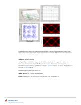
Communication-specific displays for visualizing and analyzing signals at any point or step in your model. Displays include (clockwise from top left): Channel impulse response history, I/Q signal eye diagrams, BER performance plot for theoretical vs. simulated results, and received signal scatter plot. Analog and Digital Modulation Analog and digital modulation techniques encode the information stream into a signal that is suitable for transmission. Communications System Toolbox provides a number of modulation and corresponding demodulation capabilities. These capabilities are available as MATLAB...
Open the catalog to page 3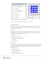
file Edit Iexl £0 Cell Teals E>e!iuq Desktop Wnciov.- help * Create a rcnacic digital nc33*qc x - randU [D K-l] , 6000, 1] ; 4 Rando* ayjnools hpemnd - BWICIL . gain35Bwl ( HMOJ h : t CTEIIC a scc::i: ploc ar.d i^cu conjrelLa.tj.n~ BeaxcerPloi; ■ cuBrasooee. ScatnerPloM1 SampleaPerSymbol', 1,. ■C□-ateLlatLoc■ r Wind. Cnna tell at ic,n) ; \ Irar-acnit aignal through an AKGH channel. ynoisv ■ awgn IY, 15, Tesjured'): * Create scatter plot Iron noisy data. upda.ee [±tat eerPlot, ymsiiy/J -, \ Demodulate ynolay to recover the MHigi. z"d«Md.uiar.e (riDetaod r yiwi IY): I cr.ee* symbol error rate....
Open the catalog to page 4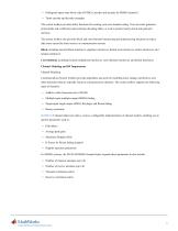
▪ Orthogonal space-time block code (OSTBC) (encoder and decoder for MIMO channels) ▪ Turbo encoder and decoder examples The system toolbox provides utility functions for creating your own channel coding. You can create generator polynomials and coefficients and syndrome decoding tables, as well as product parity-check and generator matrices. The system toolbox also provides block and convolutional interleaving and deinterleaving functions to reduce data errors caused by burst errors in a communication system: Block, including General block interleaver, algebraic interleaver, helical scan interleaver,...
Open the catalog to page 5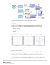
Bernoulli Binary QPSK Modulator Frame Error Rate QPSK Demodulator OSTBC Encoder Performance Display ostbc combiner Received Symbols Simulink model of an adaptive MIMO system with orthogonal space-time block codes (OSTBC). Received Signal To model the effects of a nonideal RF front end, you can introduce the following impairments into your communications system, enabling you to explore and characterize performance with real-world effects: ■ Phase and frequency offset You can include more complex RF impairments and RF circuit models in your design using SirnRF™. ideal 16 QAM scatter plot (left)...
Open the catalog to page 6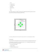
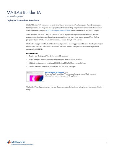
▪ LMS ▪ Normalized LMS ▪ Variable step LMS ▪ Signed LMS ▪ MLSE (Viterbi) ▪ RLS ▪ CMA These adaptive equalizers are available as nonlinear decision feedback equalizer (DFE) implementations and as linear (symbol or fractionally spaced) equalizer implementations. Scatter plot of a QPSK signal that shows the signal before and after equalization, as well as the ideal signal constellation. Synchronization The system toolbox provides algorithms for both carrier phase synchronization and timing phase synchronization. For timing phase synchronization, the system toolbox provides a MATLAB Timing Phase...
Open the catalog to page 7All The MathWorks catalogs and technical brochures
 MATLAB Production Server
6 Pages
 Database Toolbox
4 Pages
 MATLAB Report Generator
4 Pages
 Stateflow
8 Pages
 SimEvents
7 Pages
 SimDriveline
7 Pages
 SimHydraulics
7 Pages
 SimPowerSystems
8 Pages
 Simulink Control Design
5 Pages
 Aerospace Blockset
5 Pages
 SimRF
SimRF6 Pages
 Simulink Coder
6 Pages
 Embedded Coder
8 Pages
 Simulink PLC Coder
4 Pages
 Fixed-Point Designer
9 Pages
 MATLAB Coder
5 Pages
 Simulink 3D Animation
10 Pages
 Gauges Blockset
2 Pages
 Simulink Report Generator
3 Pages
 Polyspace Bug Finder
6 Pages
 global-optimization-toolbox
10 Pages
 Phased Array System Toolbox
9 Pages
 OPC Toolbox
5 Pages
 Simulink Design Verifier
7 Pages
 Simulink Design Optimization
10 Pages
 Filter Design HDL Coder
5 Pages
 Bioinformatics Toolbox
9 Pages
 SimBiology
6 Pages
 Computer Vision System Toolbox
10 Pages
 DSP System Toolbox
11 Pages
 Fuzzy Logic Toolbox
5 Pages
 Polyspace Client for C/C++
5 Pages
 xPC Target
5 Pages
 SimMechanics
7 Pages
 Simscape
7 Pages
 Simulink
6 Pages
 Data Acquisition Toolbox
8 Pages
 Image Processing Toolbox
7 Pages
 Signal Processing Toolbox
10 Pages
 Control System Toolbox
6 Pages
 Symbolic Math Toolbox?
6 Pages
 Parallel Computing Toolbox?
7 Pages
 MATLAB®
6 Pages
 Mapping Toolbox 3.2
7 Pages
 Instrument Control Toolbox
7 Pages
 Optimization Toolbox 6.0
14 Pages


Archived catalogs
 MATLAB Release Notes
505 Pages
 C and Fortran API Reference
263 Pages
 External Interfaces
649 Pages
 Function Reference: Volume 3 (P-Z)
1696 Pages
 Function Reference: Volume 2 (F-O)
1568 Pages
 Function Reference: Volume 1 (A-E)
1298 Pages
 Creating Graphical User Interfaces
520 Pages
 3-D Visualization
212 Pages
 Graphics
667 Pages
 MATLAB Programming Tips
66 Pages
 Programming Fundamentals
840 Pages
 Data Analysis
220 Pages
 Mathematics
316 Pages
 MATLAB® Getting Started Guide
250 Pages


- ERLO management software
- Automation software solution
- Analysis software solution
- Process software
- ERLO Windows software
- Real-time software
- Computer-aided design software
- Cloud-based software
- Control software
- Design software solution
- 3D software solution
- ERLO measurement software
- Visualization software solution
- Simulation software solution
- Automated software
- Programming software
- Network software
- Reporting software
- Engineering software
- Machine software