
- Catalogs
- Marsh Bellofram
- Marsh Bellofram Diversified Electronics Division TBB Series Interval DIP Switch TDR

Marsh Bellofram Diversified Electronics Division TBB Series Interval DIP Switch TDR

Marsh Bellofram Diversified Electronics Division TBB Series Interval DIP Switch TDR
- Time Delay Range: Five ranges available from 0.1 seconds to 1,023 minutes with varying increments.
- Output Rating: 10 A at 250 VAC or 24 VDC, resistive.
- Accuracy: Setting accuracy is ±2% or ±50 mSEC, whichever is greater. Repeat accuracy is ±0.1% or ±8.3 mSEC, whichever is greater.
- Reset Times: 100 mSEC before timeout, 50 mSEC after timeout.
- Supply Voltage: Options include 12, 24, 48, 120, or 240 VAC, 50/60 Hz, or DC with ±10% tolerance.
- Protection: Reverse polarity protected, no false transfer.
- Power Required: Approximately 3 VA.
- Duty Cycle: Continuous.
- Temperature Rating: Operating range from 32°F to 131°F (0°C to +55°C), storage from -49°F to 185°F (-45°C to +85°C).
- Life Expectancy: Mechanical: 10 million operations minimum; Electrical: 100,000 operations at rated load.
- Indicators: LED indicates when relay is energized.
- Isolation: 1,500 volts between input and output.
- Weight: 0.35 lbs.
When supply voltage is applied, the relay energizes and the time delay begins. The relay de-energizes upon completion of the delay period. Reset is achieved by removing the supply voltage during or after the delay period.
DIP Switch Operation: Time delay is digitally selected using ten binary switches, each marked with a time increment. The desired time delay is obtained by adding the time periods represented by each switch in the ON position.
Model TBB A is available with various control voltages and time delay ranges. Control voltages include 12V DC, 24V AC/DC, 48V DC, 120V AC/DC, and 240V AC. Time delay ranges are specified from 0.1 seconds to 1,023 minutes with different increments.
Catalog excerpts

\\\SPECIFICATIONS TIME DELAY RANGE A 0.1 to 102.3 SEC in 0.1 SEC Increments B 1.0 to 1,023 SEC in 1.0 SEC Increments C 10 to 10,230 SEC in 10 SEC Increments D 0.1 to 102.3 MIN in 0.1 MIN Increments E 1.0 top 1,023 MIN in 1.0 MIN Increments OUTPUT RATING 10 A @ 250 VAC or 24 VDC, resistive ACCURACY Setting ±2% or ±50 mSEC; whichever is greater Repeat ±0.1% or ±8.3 mSEC; whichever is greater RESET TIMES Before Time Out 100 mSEC After Time Out 50 mSEC SUPPLY VOLTAGE 12, 24, 48, 120 or 240 VAC, 50/60 Hz; or DC; ±10% FALSE TRANSFER No REVERSE POLARITY PROTECTED Yes POWER REQUIRED 3 VA, approximately DUTY CYCLE Continuous TEMPERATURE RATING Operate 32° to 131°F (0° to +55°C) Storage -49° to 185°F (-45° to +85°C) LIFE EXPECTANCY Mechanical 10 million operations, minimum Electrical 100,000 Operations @ rated load INDICATORS LED glows when relay is energized. ISOLATION 1,500 volts, input/output WEIGHT 0.35 lbs. TBB Series Diversified Electronics atcdiversified.com 800.727.5646 60Time Delay Relays // TBB Series When supply voltage is applied to the input terminals, the relay energizes and the time delay begins. Upon completion of the delay period, the relay de-energizes. Reset during or after the delay period is accomplished by removal of the supply voltage. DIP SWITCH OPERATION Digital selection of the time delay is accomplished by the use of ten (10) binary switches, each marked with a time increment. The time periods, of which there are five (5) ranges, represented by each switch in the ON position is added together to obtain the desired time delay. No more trial-by-error adjustments. I n t e r v a l D I P Sw i t c h TDR SUPPLY VOLTAGE OUTPUT TIME DELAY RB-08/PF083A \\\DIMENSIONS (INCHES) \\\WIRING MODEL NUMBER >>>>>> TBB A Control Voltage 12 D A 12 Volts DC 24 Volts AC/DC 24 A 48 Volts DC 48 D 120 Volts AC/DC 120 A 240 Volts AC 240 A Time Delay Range 0.1 to 102.3 SEC in 0.1 SEC Increments 1.0 to 1,023 SEC in 1.0 SEC Increments B 10 to 10,230 SEC in 10 SEC Increments C 0.1 to 102.3 MIN in 0.1 MIN Increments D 1.0 to 1,023 MIN in 1.0 MIN Increments E \\\OPERATION
Open the catalog to page 1All Marsh Bellofram catalogs and technical brochures
 Full Catalog BelGAS
307 Pages
 5204
52041 Page
 P627 High Flow Gas Regulator
10 Pages
 P212 Pressure Regulator
16 Pages
 P200 Pressure Regulator
19 Pages
 P95H Regulator
15 Pages
 P99 Pressure Reducing Regulator
11 Pages
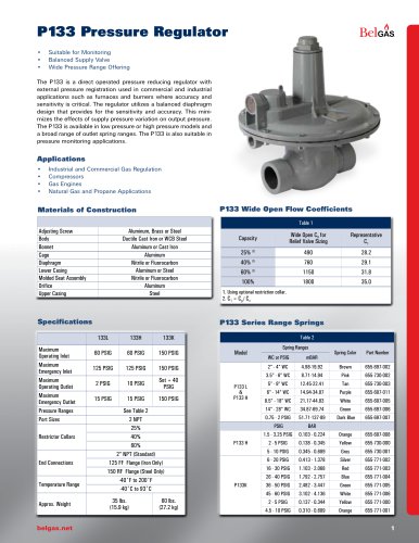 P133 Pressure Regulator
12 Pages
 P140 Pressure Regulator
4 Pages
 P303 Pressure Regulator
11 Pages
 P300 Pressure Regulator
11 Pages
 P203 Pressure Reducing Regulator
18 Pages
 F300 Pressure Regulator
7 Pages
 P600 Pressure Regulator
7 Pages
 P289RC Exhaust Booster
2 Pages
 W627 Liquid Gas Regulator
8 Pages
 F627 High Flow Gas Regulator
7 Pages
 BELLOFOAM™ 7804
1 Page
 BELLOFOAM™ 7704
1 Page
 BELLOFOAM™ 7604
1 Page
 Marsh Catalog
84 Pages
 P79 Air Relays
4 Pages
 Automated Timing & Controls
142 Pages
 Motor Protection
86 Pages
 Digital Controllers
30 Pages
 P630 High Flow Gas Regulator
12 Pages
 P39 Standard Gas Regulators
4 Pages
 P40 & P40 NACE Regulators
2 Pages
 P912 Pressure Regulator
2 Pages
 P119 Control Valve
4 Pages
 BelGAS Product Overview LT5040
12 Pages
 KING-GAGE Product Catalog
12 Pages
 BelGas P200 Pressure Regulator
18 Pages




Archived catalogs




- Valve
- Connector
- Manual valve
- Cylinder
- Temperature probe
- Electrical power supply connector
- On/off valve
- Angular encoder
- Incremental encoder
- Pressure gauge
- Pressure limiter
- Gas valve
- Double-acting cylinder
- Profile
- Level probe
- Switching relay
- Single-stage pressure regulator
- Liquid level sensor
- Incremental rotary encoder
- Rectangular connector