
- Catalogs
- Marsh Bellofram
- Automated Timing & Controls

Automated Timing & Controls

Automated Timing & Controls
- Specifications: Features 13 functions and 10 time ranges, with a supply voltage of 20-240V AC/DC. It is designed for DIN rail mounting with an IP40 protection level.
- Functions: Includes modes such as On delay, Interval, and Cyclic equal OFF first.
- Time Ranges: From 0.1 seconds to 3 hours.
- Accuracy: Setting accuracy is ±5% of full scale, with repeat accuracy of ±0.5%.
- Specifications: Designed for On delay mode with 10 time ranges, operating at 110V AC.
- Protection: NEMA 12 level protection.
- Specifications: Offers 15 functions and 8 time ranges, with a universal supply voltage of 20-240V AC/DC.
- Functions: Includes modes such as Asymmetrical cyclic OFF first and Pulse output.
- Accuracy: Setting accuracy is ±0.1% of set time or ±50mSec.
- Operations: Conductive liquid level controller with modes for Drain (Pump Down) and Fill (Pump Up).
- Specifications: Adjustable sensitivity, operates with a supply voltage of 24V, 120V, or 240V AC.
- Specifications: Continuous ON-OFF control with time ranges of 30, 60 seconds, and 15, 30, 60 minutes.
- Applications: Suitable for controlling pumps, blowers, filters, and heating equipment.
- Specifications: Available in plug-in and non-plug-in models with time cycles of 15, 30, and 60 seconds.
- Features: Rugged design with self-cleaning silver contacts and continuous adjustment of on time between 5% and 95%.
The document outlines specifications for various timer models, including load relay, power requirements, terminals, and weight. Key specifications include:
- Load Relay: SPST Relay 10 Amp @ 120 VAC.
- Power Requirements: 120V, 50/60 Hz; 50mA running current.
- Terminals: 4 screw terminals accessible at the rear.
- Weight: Net 5-6 oz, Shipping 1 lb.
The 304GX model offers enhanced accuracy and features such as:
- Improved accuracy to 1% of range.
- Cycle Progress Memory: Continues cycle without resetting after power interruption.
- High Accuracy: Utilizes a microprocessor with a stable crystal oscillator.
- Convenient Adjustment: Graduated in 1% increments for on-time adjustment.
The 305E series is noted for its circuit flexibility and high accuracy:
- Repeat accuracy of 0.2%.
- Plug-in and dust-tight design.
- Fastest reset time of 0.1 seconds.
- Long mechanical life expectancy of over 5,000,000 operations.
The 322B series offers a dial-adjustable TDR with cycle progress indication:
- Repeat accuracy of 2% of dial range.
- Reset time of 150 ms.
- Life expectancy of 2,500,000 cycles.
- Instantaneous and delayed load switches for versatile timing functions.
The document provides detailed instructions on configuring the timers using jumpers and wiring diagrams. It includes:
- User configuration charts for setting ranges.
- Instructions for ON-Delay and OFF-Delay operations.
- Wiring diagrams for terminal connections.
The timers are suitable for various applications requiring precise timing control, such as industrial automation and process control.
- Operation: The timer is manually set to a desired time. When the knob is turned from zero, switch MS closes, energizing load A. After the set time, the load is de-energized, and the timer stops at zero. Terminal 4 can connect to load B for an end-of-cycle signal.
- Applications: Suitable for controlling electrical circuits in processing machinery, plastic molding, laundry equipment, electric ovens, and more.
- Specifications: Time ranges from 1 minute to 24 hours, SPDT output, 15A, 240 VAC resistive, motor voltages of 120 VAC, 240 VAC, 60 Hz, and a temperature rating of 32° to 120°F.
- Cycle Times: Offers ON-Delay or OFF-Delay operation with over 270 cycle times ranging from 9 seconds to 60 hours.
- Accuracy: Repeat and setting accuracy within ±0.25% of cycle time.
- Construction: Features a split-cam design for precise adjustments, with cams made of Delrin.
- Specifications: SPDT precision switches rated at 10 amps, 120 VAC, with a wide range of cycle times available through interchangeable gears.
- Drive Motors: Synchronous motors with a choice of 12 speeds, voltage options of 120 VAC or 240 VAC, and power consumption of 12 watts max.
Model S2X is rated at 10A @ 230 VAC/24 VDC, resistive, while Model S5TX is rated at 5A @ 230 VAC/24 VDC, resistive.
Setting accuracy is ±5% of full scale. Repeat accuracy is ±0.5% or 50 msec, whichever is greater.
Operating temperature ranges from 32° to 122°F (0° to 50°C), and storage temperature ranges from -4° to 167°F (-20° to 75°C).
The 405AR offers selectable ON-Delay or Interval Mode operation with a DPDT 10A contact output. In On-Delay mode, contacts transfer at timeout, while in Interval mode, contacts transfer when power is applied and release at timeout.
The 405AR features a compact 48mm2 housing with an IP40 rated front cover. It can be mounted in an 8-pin round socket or panel mounted. Mode/Range select dip switches are located on the front under a clear cover.
The 405AR can be powered by 20 to 240 VAC or 12 to 240 VDC, reducing inventory management of replacement units.
Switch settings allow for selection of timing ranges from 1 second to 30 hours and modes such as On-Delay and Interval.
Various models like 405C100F1X and 405C500F1X offer features such as instantaneous and delayed relays, selectable timing modes, and universal power supply. They are available in six timing ranges from 1 second to 50 hours.
Contacts are rated at 10 AMPS resistive at 30 VDC or 250 VAC, with a life of 10 million operations with no load and 100,000 operations with load.
Universal power supply with reverse polarity protection, accepting 24 to 240 VAC, 50 or 60 Hz, and 24 VDC.
Includes features like a large, easy-to-read dial, tamper-proof range and mode select switches, and unique flashing cycle progress indication.
The document outlines specifications for various timer models, including voltage ratings, contact ratings, and operational life. The timers are rated for 1/8 HP at 120 VAC and 1/4 HP at 240 VAC, with a life expectancy of 10 million operations without load and 100,000 operations with specified loads. Contact material is silver nickel, and the operating temperature range is 0° to 122°F (-18°C to 50°C).
Mounting Options:
Timers can be mounted using plug-in bases, surface mounting sockets, DIN rail mounting sockets, or panel-mounting adapter kits. The universal power supply accepts 24 to 240 VAC or 24 VDC, with specific inrush current and power requirements.
Operational Features:
The timers feature high accuracy with variations depending on temperature and voltage. They include push-button start, interval timing modes, and tamper-proof range selection when panel-mounted. The timers are equipped with DPDT or SPDT relay outputs, depending on the model.
Model Specifics:
- 409 Series: Features push-button start, interval timing, and six timing ranges. It is housed in a compact 1/16 DIN size and can be mounted in various ways.
- 417 Series: Designed for rugged environments with true off-delay operation and high noise immunity. It offers three timing ranges and can be reset remotely.
- 422AR Series: Offers repeat cycle operations with adjustable ON and OFF times. It is suitable for periodic cycling of loads and features LED indicators for cycle progress.
- 425 Series: Digital setting with high accuracy and a bright LED display for cycle progress indication. It allows for precise and repeatable timing cycles.
Applications and Accessories:
The timers are suitable for industrial applications requiring precise timing and control. Accessories include various mounting sockets and brackets to facilitate installation.
- Model 425A300Q10XX: Features SPDT instantaneous and delayed relays. Timing starts when power is applied, with an LED display indicating progress. The timer remains in a timed-out condition until reset by removing power.
- Model 425A300Q20XX: Similar to the 10XX model but with DPDT delayed contacts. The operation is identical, with timing starting upon power application and the timer remaining in a timed-out condition until reset.
- Memory Option: Models with EEPROM memory retain elapsed time during power interruptions and require manual reset after time-out.
- Display and Controls: High-intensity green LED display, tamper-proof switch selectable timing ranges, and timing LED indicating relay status.
- Environmental and Electrical Ratings: Operates within 0° to 140°F, with noise immunity per NEMA standards, and requires 120 VAC power.
- 5708A Series: A multifunction timer-counter with 23 selectable functions, including timer, counter, frequency meter, and tachometer. It features a high-resolution LCD and is battery-operated.
- 7DT-2CH Series: A DIN rail-mounted timer suitable for daily or weekly schedules, featuring two independent channels and a clear LCD display.
- Easy-to-read LED displays and tamper-proof controls.
- EEPROM memory for power interruption resilience.
- Multiple mounting options including panel and plug-in sockets.
- High accuracy and repeatability in timing operations.
- Timing Range: Adjustable between 0.02 seconds and 30 minutes, with five fixed ranges from 1 to 30 seconds.
- Cycle Progress Indication: Features LEDs for timing and output relay status.
- Accuracy: High repeat accuracy despite voltage and temperature variations, with a reset time of 0.1 seconds between cycles.
- Specifications: Operates on 24-240 VAC or 24 VDC, with a DPDT load relay type and a contact rating of 7A at 120 or 240V AC.
- Timing Range: Offers six switch-selected ranges from 1 second to 10 hours.
- Operation Modes: Supports ON-delay, OFF-delay, and interval operations.
- Accuracy: Maintains high accuracy with a digital circuit, unaffected by reset time.
- Specifications: Operates on 24 VAC to 240 VAC and 24 VDC, with a DPDT load relay type and a contact rating of 10A at 125-250V AC.
- Timing Range: Available in eight fixed ranges from 0.3 seconds to 3 minutes.
- Design: Economical and rugged, suitable for industrial environments.
- Accuracy: Utilizes a proprietary integrated circuit for high accuracy.
- Specifications: Operates on 120 VAC, 50/60 Hz, with a DPDT load relay type and a contact rating of 5A at 30 VDC or 240 VAC.
- Timing Range: Offers six dial-selected ranges from 0.3 seconds to 10 hours.
- Operation Modes: Supports selectable on-delay or interval timing modes.
- Cycle Progress Indication: Features an LED that blinks at an increasing rate as the cycle progresses.
- Accuracy: Maintains high accuracy despite voltage and temperature variations.
- All models are designed for industrial service with high impact-resistant housings and plug-in bases for easy mounting.
- Each model provides specific accessories for mounting and installation, ensuring versatility and ease of use.
- Features counting technology and a stable oscillator for repeatable time delays.
- Supports multiple timing modes: on-delay and interval timing, selectable via a switch.
- Timing begins with the closure of a start switch, activating an oscillator that determines the cycle's end based on frequency.
- LED indicators show cycle progress and completion.
- Available in various voltage and frequency configurations (120 VAC, 240 VAC, 24 VAC/DC, 12 VDC).
- Includes accessories like sockets and hold-downs for mounting.
- Solid-state flasher with a 50% duty cycle and factory-fixed timing range (45-150 flashes per minute).
- Operates with 120 VAC supply voltage and features encapsulated circuitry for environmental protection.
- Designed for continuous ON/OFF cycling until supply voltage is removed.
- These series feature DIP switch operation for digital selection of time delays, eliminating trial-and-error adjustments.
- Time delay ranges vary from 0.1 seconds to over 10,000 seconds or minutes, depending on the model.
- Output ratings typically include 10 A at 250 VAC or 24 VDC, with options for SPDT and DPDT configurations.
- Designed for continuous duty cycles with high mechanical and electrical life expectancy.
- Include features like reverse polarity protection, LED indicators, and isolation up to 1,500 volts.
- All models are designed to operate within specific temperature ranges and voltage requirements.
- Accuracy and repeatability are specified, with variations depending on line voltage and temperature conditions.
- Mounting options include plug-in bases, surface mounting, and DIN rail mounting.
The document outlines the specifications for a series of time delay relays. The operating temperature range is 32° to 131°F (0° to +55°C), with a storage range of -49° to 185°F (-45° to +85°C). The mechanical life expectancy is a minimum of 10 million operations, while the electrical expectancy is 100,000 operations at the rated load. The relays have an isolation of 1,500 volts between input and output and weigh approximately 0.4 lbs.
The relays operate by cycling between ON and OFF states. When supply voltage is applied, the OFF time (T1) begins, followed by the ON time (T2) once T1 is complete. This cycle continues until the supply voltage is removed. The time periods for ON and OFF states are independently selectable within the same range.
Time delay is digitally selected using ten binary switches, each marked with a time increment. The time periods are available in five ranges, and the desired delay is achieved by adding the increments of switches in the ON position.
The document specifies several time delay ranges: 0.1 to 102.3 seconds in 0.1-second increments, 1.0 to 1,023 seconds in 1.0-second increments, 10 to 10,230 seconds in 10-second increments, 0.1 to 102.3 minutes in 0.1-minute increments, and 1.0 to 1,023 minutes in 1.0-minute increments.
The relays are available with control voltages of 12 VDC, 24 VAC/DC, 48 VDC, 120 VAC/DC, and 240 VAC. Model numbers are provided for different configurations and series, such as TBF, TBG, TBL, and TBU.
The relays feature LED indicators that glow when energized, reverse polarity protection, and are designed for continuous duty cycles. They require approximately 3 VA of power and have a reset time of 100 mSEC before timeout and 50 mSEC after timeout.
The document describes various modes of operation, including interval, on-delay, off-delay, single-shot, and flasher modes. Each mode has specific wiring and operational characteristics, such as the initiation of time delays and reset conditions.
- Supply Voltage: Available in 24 VAC/DC and 110/120 VAC/DC.
- Output Rating: DPDT, 10 A @ 250 VAC or 24 VDC, resistive; 211 VA @ 120 VAC, inductive.
- Timing Ranges: Virtually unlimited, with specific ranges detailed on page 76.
- Temperature Rating: Operate between 32°F to 131°F (0°C to +55°C); Storage between -49°F to 185°F (-45°C to +85°C).
- Life Expectancy: Mechanical - 10 million operations; Electrical - 100,000 operations at rated load.
- Interval on Operate: Voltage is applied continuously; an external switch controls the timer. The relay energizes when the switch is closed and de-energizes after the delay period.
- Delay on Release: Similar to interval on operate, but the relay de-energizes upon switch opening.
- Single-Shot: The relay energizes and begins the delay period upon switch closure, de-energizing after the delay.
- Repeat Cycle: Alternates between ON and OFF periods, continuing until voltage is removed.
- 8-pin or 11-pin round plug-in.
- Blade plug-in.
- Some options, like the 'R' option, are not UL recognized and have specific availability constraints.
- Models are available with different types of operation adjustments: knob adjustable, lock nut adjustable, fixed, and external resistor adjustable.
The document outlines various timer relay models with specifications including timing ranges, output ratings, duty cycles, supply voltages, and life expectancy. The timing ranges are virtually unlimited, with standard ranges available on page 76. The output is DPDT, rated at 10 A @ 250 VAC or 24 VDC, resistive, and 211 VA @ 120 VAC, inductive. The supply voltage options are 24 or 120 VAC or VDC, 50/60 Hz, with a tolerance of ±10%. The power consumption is approximately 3 watts, and the temperature rating for operation is 32° to 131°F (0° to +55°C), with storage temperatures ranging from -49° to 185°F (-45° to +85°C). Mechanical life expectancy is 10 million operations, while electrical life expectancy is 100,000 operations at rated load.
The operation of the timers involves applying voltage to the input, which energizes the internal relay and begins the time delay. The document describes different modes of operation such as ON-Delay, OFF-Delay, Single Shot, and Flasher modes. Each mode has specific instructions on how the relay behaves when voltage is applied or removed, and how the time delay is initiated and reset.
The document provides wiring diagrams and dimensions for various plug-in styles, including octal and blade plug-ins. The dimensions are typically 2.375 inches by 1.75 inches.
It is recommended not to program with power on and to wire for one timing range only. The document also advises on the use of external resistors for adjustable delay periods, specifying that a 1/4 watt or larger resistor should be used.
The document includes a standard delay range chart, showing minimum and maximum settings for various suffixes, such as 010 for 0.1 to 10 seconds and 300 for 3 to 300 seconds. It also provides a formula for determining the external resistance value required for a specific time delay.
- The Shawnee 355 timer is housed in a compact 72mm2 DIN-size casing, offering a 40% reduction in panel space and a 45% cost saving compared to previous models.
- It boasts outstanding repeat accuracy of ±10 milliseconds and is immune to electrical noise, making it suitable for industrial environments.
- The timer operates on a digital logic circuit with a clock, ROM, and comparator, and requires a reset time of 75 milliseconds.
- Available in various ranges (e.g., 0.01 - 99.99 SEC/MIN) and voltage options (120/240 VAC, 50/60 Hz).
- The Shawnee 355 operates in an On-Delay mode, resetting automatically during power outages and starting a new cycle when power is restored.
- The LED display indicates cycle progress, counting up from zero during the timing cycle.
- Model numbers and configurations vary based on range, voltage, and features, such as display options and plug-in units.
- The ATC 365 is a microprocessor-based digital timer with a wide range of 0.01 SEC to 999 HR, featuring three rotary knobs for setting adjustments.
- It offers programmable display options, noise immunity, and reliability with a life expectancy of 100 million operations for its load relays.
- The timer is compact, plug-in, and dust-tight, designed for easy replacement without disturbing field wiring.
- Detailed wiring diagrams and installation instructions are provided for both sustained and momentary start configurations.
- Maximum load current through any contact is 5 amperes, with pilot lights available for various function indications.
- Optional accessories include surface mounting bracket kits and retrofit kits for both timer series.
The document describes the features and specifications of the 365M and 385A series digital timers from Automatic Timing & Controls. The 365M series offers nine switch-selectable timing ranges from 0 to 999 seconds, minutes, or hours. It features a high-intensity blue fluorescent display, magnetic latch relay, and EEPROM memory for non-volatile data retention. The 385A series is a multifunction timer/counter with a dual LED display, capable of timing in hours:minutes and minutes:seconds, and counting up to 99,900 in two ranges.
Procedures:
The 365M series allows easy adjustment of preset times using three rotary switches, even during a timing cycle. The 385A series setup involves DIP switches for programming presets and modes of operation. Both series support multiple starting options and relay actions.
Norms and Standards:
The timers are designed for 50 or 60 Hz power operation and are self-calibrating. They are housed in a 72mm2 DIN size, fully gasketed for dust-tight protection when panel mounted.
Recommendations:
For optimal use, the 365M series should be used in applications requiring high accuracy and noise immunity. The 385A series is recommended for applications needing versatile timing and counting functions with programmable input scaling.
Key Features:
- Easy-to-adjust presets with rotary switches (365M)
- Self-calibrating microprocessor
- Programmable display modes
- Magnetic latch relay and non-volatile EEPROM memory
- Dual DPDT relays rated at 7A
- Compact, plug-in design for easy installation
Limitations:
The 385A series does not implement arrangement 3 mode, but most functions can be achieved with the flip-flop mode. The maximum setting for hours:minutes and minutes:seconds is 99:59.
Good Practices:
Ensure proper setup of DIP switches for desired operation modes and regularly check the display for cycle progress and preset adjustments.
The document outlines the specifications for various panel-mounted digital timers, including models 385AR, 425AR, 652, 653, and 655 series. Key specifications include:
- Accuracy: ±0.05% of setting for timers, ±0 counts for counters.
- Scale Factor: 0.001 to 9.999 x 10^n (n = -3 to 2).
- Reset Options: Front, remote, power interruption.
- Sensor Supply: Built-in, 12V DC, 30mA, short circuit protected.
- Output: 2 SPST (2 NO) relays, rated at 5A @ 230V AC.
- Operating Modes: Various modes including ON delay, interval, cyclic, batch, and more.
- Timer Range: 0-9999 seconds/minutes/hours.
- Counter Range: -999 to 9999 counts.
- Memory Retention: Yes, with EEPROM or lithium battery options.
- Supply Voltage: 85 to 270V AC/DC, 50/60Hz.
- Power Consumption: 5VA max.
- Temperature/Humidity: Operating 0 to 50°C, storage -20 to 75°C, 95% RH non-condensing.
- Protection Level: IP65 for faceplate.
The document provides detailed procedures for setting up and operating the timers, including:
- Wiring instructions with terminal connections and cable specifications.
- Programming instructions using DIP switches and front panel keypads.
- Reset and start procedures for various timing modes.
The timers comply with various electrical standards, ensuring reliable operation across different environments. They are designed to replace most electromechanical timers and fit into existing setups without major modifications.
For optimal performance, it is recommended to:
- Consult the factory for specific model configurations and voltage requirements.
- Use the provided mounting brackets and gaskets for secure installation.
- Follow the DIP switch setting guide for accurate timing mode and range selection.
The document includes timing diagrams illustrating the operation of various modes such as ON delay, interval, cyclic ON/OFF, and batch functions. It also provides a DIP switch setting guide for configuring the timers according to specific model numbers.
- 655 Series: Offers timing from 0.001 seconds to 199 hours 59 minutes with modes like ON-Delay and Reverse Start Delay. It features a reset time of 25 mSEC and operates on 120 or 240 VAC.
- 765 Series: A programmable step controller with up to 100 steps and 8 relay outputs. It supports multiple timing ranges and is equipped with EEPROM memory for data retention.
- CS100 Series: A repeat cycle timer with selectable timing ranges (T1, T2, T3) and solid-state relay outputs. It is designed for easy replacement and synchronization with other units.
- 354C Series: A high-speed counter with a range of up to 99,990 counts. It features noise immunity, plug-in design, and selectable bounce suppression levels.
- For the 655 series, the preset time can be changed during a cycle, but the new setting will only apply to the next cycle. The ENT button must be pressed to return to operating mode after setting the time.
- The 765 series allows for easy configuration via a membrane keypad and is suitable for harsh environments. It can advance steps based on time or count inputs.
- The CS100 series provides quick access to timing settings through front push-buttons and allows for synchronization of multiple units.
- The 354C series operates on digital logic circuits and offers various control actions based on wiring configurations. It is designed to be dust-tight and occupies less panel space.
- All models are designed for industrial use with features like NEMA ratings, transient voltage protection, and robust mechanical life.
- They offer high accuracy and reliability, with some models providing memory retention without battery backup.
- Display features include LCD or LED readouts for easy monitoring of operational status and settings.
- Noise Immunity: The 366 series counters are equipped with full-wave bridges and transformer power supplies to block industrial noise, ensuring accurate counting without the need for shielding.
- Computation: The internal microcomputer allows for real-time recomputation of counts, enabling cycle adjustments without accuracy loss.
- Programmable Display: The display can be set to count up or down, with options to continue counting after reaching the set point.
- Wide Range: The counter covers a span of 1 to 99,900 counts, with selectable ranges for optimization.
- Self-Diagnostics: Built-in diagnostics verify the functionality of the counter's circuits without external instruments.
- Compact Design: The 366 series is housed in a compact, dust-tight, and water-tight design, occupying minimal panel space.
- Display: High-intensity blue fluorescent display with a three-digit cycle progress indicator.
- Reset Time: Consistent reset time clocked at 40 mSEC.
- Count Input: Supports both AC and DC inputs with specific pulse on/off times and bounce immunity.
- Load Relay: Includes one instantaneous and one delayed relay with specific contact ratings.
- Power Requirements: Operates on various AC and DC voltages with specified inrush and running currents.
- High-Speed Counting: Capable of counting at a maximum frequency of 10 kHz, with debounce circuit options.
- Counting Modes: Available in Single and Dual Preset models, with options for batch counting and interval counting modes.
- Inputs/Outputs: Supports uni- and bi-directional counting, quadrature inputs, and various output configurations.
- Operator Panel: Features a dust and water-tight panel with a high-intensity blue display and easy-to-use snap-action keys.
- Set-Up: Utilizes DIP switches for straightforward setup and quick field replacement.
- Display: 6-digit count display with English language prompts.
- Prescaler: Allows setting of prescale values for real unit measurements.
- Auxiliary Power Supply: Provides regulated 12 VDC power for sensor and encoder inputs.
The document outlines the specifications for various models of counters and controllers, including single and dual preset counters, PID temperature controllers, and solid-state relays. Key specifications include input types, output types, operating modes, and environmental conditions such as temperature and humidity ranges.
Counter Modes and Features:
The counters operate in different modes such as Interval Mode, Batch Mode, and Timed Outputs. Interval Mode requires a start signal to begin counting, while Batch Mode records counts based on preset values. Timed Outputs allow for delayed deactivation of outputs. The counters also feature a scale factor for adjusting count displays and settings.
PID Temperature Controllers:
The PID controllers offer dual display, selectable temperature units (°C/°F), and various control actions including PID and ON-OFF. They support multiple input types like thermocouples and RTDs, and feature settings for proportional, integral, and derivative times.
Solid-State Relays:
The solid-state relays are available with DC and AC inputs, supporting various output voltages and currents. They include features like LED operation indicators and require heat sinks for optimal performance.
Wiring and Installation:
The document provides detailed wiring instructions and terminal connections for the devices. It also includes information on mounting options and accessories like surface mounting brackets.
Compliance and Standards:
The devices comply with standards such as IEC/EN 61326 for EMI/EMC and IEC/EN 61010 for safety. Specific models have UL recognition.
Additional Features:
Other features include non-volatile memory for data retention, security lockout for preset access, and various reset options. The document also details the dimensions and weight of the devices, ensuring compatibility with different installation environments.
- The accessory part includes a bracket and an integral terminal strip for surface mounting and convenient terminal access.
- Dimensions are provided in inches and millimeters for series 353, 354, 355, 356, 365, 366, 376, and 385.
- 72mm2 Panel Mounting Adapter Kits: These kits facilitate the mounting of newer 72mm2 units into existing panel cutouts. They are available for round and square cutouts from various older products.
- 1/16 DIN Panel Mounting Adapter Kits: Designed for 1/16 DIN (48mm2) standard housing styles, these kits allow for retrofitting and mounting of multiple units side by side.
- 305-265-61-70: Retrofit kit for round cutouts from Eagle Signal and ATC series.
- 376-320-01-00: Retrofit kit for square cutouts from Red Lion, Eagle Signal, Veeder Root, and Durant series.
- 405-320-03-00, 405-320-06-00, 405-320-05-00: Kits for mounting single, two, or four units respectively.
- 1/16 DIN Timer Accessories include various 8-pin and 11-pin accessories for panel and DIN rail mounting.
- Specific part numbers are provided for hold-downs, sockets, and plug-on socket kits.
- 101026105: A linear taper potentiometer recommended for use with ATC Diversified Electronics timers.
- 100054073: A knob for adjustments or switches with a 1/4" shaft, featuring a knurled, mirror-finished design.
Catalog excerpts

SPECIFICATIONS ACCURACY Setting: ±5% of FS Repeat: ±0 5% (FS = Full Scale) Reset time < 100 msec OUTPUT CONTACT On delay (A) Interval (B) Cyclic equal OFF first (C) Cyclic equal ON first (Ci) Pulse output, 500ms fixed (D) Delay on break (E) Delay on make / Delay on break (F) Interval after break (H) Single shot (I) Retriggerable Single shot (J) Latching relay (K) Delay with Totalize (Ai) Interval with Totalize (Bi) TIME RANGES SUPPLY VOLTAGE POWER CONSUMPTION Multi-Function Timer • 13 Functions • 10 Time Ranges • Front knobs for Time Range, Time Scale & Mode Setting • Slim, Space Saving Design...
Open the catalog to page 2
Supply Voltage Function: Cyclic Equal OFF First (C) Supply Voltage Start Supply Voltage Control Contact (Y1) Function: Cyclic Equal ON First (Ci) Function: Pulse Output (D) Supply Voltage TIMING DIAGRAMS Function: Delay On Break (E) Supply Voltage (U) Supply Voltage Function: Delay On Make / Break (F) Function: Interval After Break (H) Function: Single Shot (I) Function: Retriggerable Single Shot (J) Function: Latching Relay (K) Function: Delay With Totalize (Ai)
Open the catalog to page 3
ACCURACY RESET TIME RANGES POWER CONSUMPTION • 10 Time Ranges • Front knobs for Time Range & Time Scale • Slim, Space Saving Design PROTECTION LEVEL CONTACT RATING Single Mode Timer Reset time < 100 msec OUTPUT CONTACT Setting: ±5% of FS Repeat: ±0 5% (FS = Full Scale) TIMING DIAGRAM Supply Voltage T = set time 17.5 mm Symmetrical 35mm Din Rail (EN50022) Mounting ORDERING INFORMATION PART NO. 175SO-110 Cable Size (AWG): 16 ; Tightening Torque (Lb-inch): 4.5 Cable Size (mm2): 1.5 ; Tightening Torque (N-m): 0.5 Automatic Timing & Controls
Open the catalog to page 4
Setting: ±0 1% of set time of ±50mSec Repeat: ±0 1% Reset time < 100 msec, Front Key, Interruption of Power OUTPUT CONTACT CONTACT RATING 8A @ 250V AC MODES On delay (A) Interval (B) Asymmetrical cyclic OFF first (C) Asymmetrical cyclic ON first (D) Cyclic equal OFF first (E) Cyclic equal ON first (F) Pulse output (H) Delay on break (J) Delay on make/break (K) Interval after break (L) Single shot (P) Retriggerable Single shot (Q) Latching relay (R) Delay with Totalise (t) Interval with Totalise (U) TIME RANGES POWER CONSUMPTION • 15 Functions • 8 Time Ranges • Front Key Pad Setting • Universal...
Open the catalog to page 5
TIMING DIAGRAMS Function: Asymmetrical Cyclic OFF First (C) Function: Cyclic Equal OFF First (E) Function: Cyclic Equal ON First (F) Function: Pulse Output (H) Function: Delay On Break (J) Supply Voltage Function: Delay On Make / Break (K) Function: Interval After Break (L) Function: Single Shot (P) Supply Voltage Control Contact Function: Retriggabie Single Shot (Q) Function: Latching Relay (R) Supply Voltage Function: Delay With Totalise (T) Supply Voltage Function: Interval With Totalise (U) Automatic Timing & Controls 800.727.5646 automatictiming.com
Open the catalog to page 6
The ATC Diversified LPC Series is a conductive liquid level controller that uses two probes to sense tank level There are two modes of operation that are user selectable Drain (Pump Down): The output relay will pick-up and the LED will turn on when the liquid level reaches the high level probe When the liquid level falls below the low level probe the relay will drop-out and the LED will turn off Fill (Pump UP): The output relay will pick-up and the LED will turn on when the liquid level falls below the low level probe When the liquid level reaches the high level probe the relay will drop-out...
Open the catalog to page 7
Automatic Timing & Controls
Open the catalog to page 8
• Precise Fool-proof Operating Mechanism • Eliminates All Engaging Cams and Latches • Five Time Ranges from Which to Choose 120 VAC • Minimal Panel Space Needed APPLICATIONS: Control of pumps, blowers, filters, heating equipment, industrial ovens, laboratory equipment and wherever ON or OFF control is desired as a percentage of the primary fixed total time cycle Percentage Timer SPECIFICATIONS TIME RANGES Continuous ON-OFF RANGE SETTING SETTING ACCURACY Within 2% of Full Scale REPEAT ACCURACY Within 1% of Full Scale MOTOR VOLTAGES 120 VAC 50/60 Hz , 240 VAC, 50/60 Hz (50 Hz Units Will Be 1/6...
Open the catalog to page 9
PERCENTAGE TIMER Easily the most rugged and dependable of industrial percentage timers, the ATC 304 incorporates heavy-duty contacts that are capable of switching loads as large as 4 6 KW directly LARGE CONTACTS: Self-cleaning silver contacts are 3/8 inch in diameter, larger than in any other make of percentage timer They easily provide 1,000,000 operations at the full rated load of 25 A (non plug-in models) Percentage Timer OPERATION The 304 is available in a choice of 15, 30 and 60-second time cycles (60 Hz) Its synchronous motor drives a cam which repeatedly closes the SPST load switch for...
Open the catalog to page 10
» MODEL NUMBER MODEL NUMBER VOLTAGE & FREQUENCY Standard plug-in timer Standard non-plug-in timer With hold switch MODEL NUMBER VOLTAGE & FREQUENCY Metal Dial STANDARD UNIT/NON-PLUG-IN With hold switch DIAL CALIBRATION DIAL CALIBRATION DIMENSIONS (INCHES/MILLIMETERS) PANEL CUSTOMER'S PANEL PANEL DRILLING PANEL DRILLING CUSTOMER'S PANEL Automatic Timing & Controls 800.727.5646 automatictiming.com
Open the catalog to page 11
PERCENTAGE TIMER The 304G solid-state percentage timer comes standard in a 120 SEC range with 15 SEC, 30 SEC, 60 SEC user configurable ranges Additionally, all second ranges can become minute ranges by changing jumper J11 The 304G is easily panel mounted with 4 screws It utilizes an integrated circuit technology for high accuracy timing CONTACTS: The relay contact is capable of switching 10 A to a resistive 120 VAC or 30 VDC load It is capable of driving a 1/3 HP load at 120 VAC Solid-State Percentage Timer CYCLE PROGRESS INDICATION: The 304G has a pilot light that is on solid during the relay...
Open the catalog to page 12
DIMENSIONS (INCHES) PANEL CUTOUT CUSTOMER'S PANEL INDUSTRIAL CONTROL Contact Rating AutomaticTiming & Controls , REAR VIEW OF TIMER *For same minute ranges, install JP11 1. Jump JP13, No Jump JP11, JP12, make a 120 SEC range. 2. Jump JP11, No Jump JP12, JP13, make a 60 minute range. USER CONFIGURATION Automatic Timing & Controls 800.727.5646 automatictiming.com
Open the catalog to page 13All Marsh Bellofram catalogs and technical brochures
 Full Catalog BelGAS
307 Pages
 5204
52041 Page
 P627 High Flow Gas Regulator
10 Pages
 P212 Pressure Regulator
16 Pages
 P200 Pressure Regulator
19 Pages
 P95H Regulator
15 Pages
 P99 Pressure Reducing Regulator
11 Pages
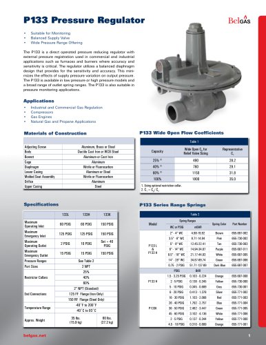 P133 Pressure Regulator
12 Pages
 P140 Pressure Regulator
4 Pages
 P303 Pressure Regulator
11 Pages
 P300 Pressure Regulator
11 Pages
 P203 Pressure Reducing Regulator
18 Pages
 F300 Pressure Regulator
7 Pages
 P600 Pressure Regulator
7 Pages
 P289RC Exhaust Booster
2 Pages
 W627 Liquid Gas Regulator
8 Pages
 F627 High Flow Gas Regulator
7 Pages
 BELLOFOAM™ 7804
1 Page
 BELLOFOAM™ 7704
1 Page
 BELLOFOAM™ 7604
1 Page
 Marsh Catalog
84 Pages
 P79 Air Relays
4 Pages
 Motor Protection
86 Pages
 Digital Controllers
30 Pages
 P630 High Flow Gas Regulator
12 Pages
 P39 Standard Gas Regulators
4 Pages
 P40 & P40 NACE Regulators
2 Pages
 P912 Pressure Regulator
2 Pages
 P119 Control Valve
4 Pages
 BelGAS Product Overview LT5040
12 Pages
 KING-GAGE Product Catalog
12 Pages
 BelGas P200 Pressure Regulator
18 Pages




Archived catalogs




- Valve
- Connector
- Manual valve
- Cylinder
- Temperature probe
- Electrical power supply connector
- On/off valve
- Angular encoder
- Incremental encoder
- Pressure gauge
- Pressure limiter
- Gas valve
- Double-acting cylinder
- Profile
- Level probe
- Single-stage pressure regulator
- Switching relay
- Liquid level sensor
- Incremental rotary encoder
- Pneumatic cylinder