- Catalogs
- MANKENBERG GmbH
- catalogue

catalogue
catalogue
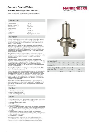
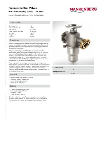
- DM 152: Suitable for small to medium flow rates, applicable for liquids, gases, and steam. Made from CrNiMo steel, corrosion-resistant, and maintenance-friendly.
- DM 3, 4: Designed for medium to large flow rates with high accuracy and adjustable damping. Made from GG-20 or GS-C 25.
- DM 401: High-pressure valve for steam, robust and suitable for high temperatures.
- DM 462 & 462V: Valves for large flow rates, applicable for liquids, gases, and steam, with options for pneumatic control.
- DM 502: Standard valve for CO2, made from stainless steel and brass, with various control ranges.
- DM 505, 505Z: Valves for small flow rates, corrosion-resistant, and available in various configurations.
- DM 506: Small pressure reducer, cost-effective, and suitable for liquids and gases.
- DM 510 - 518: High-pressure valves with variable throughput and connection options.
- DM 603, 604, 613: Standard cast valves for various applications, made from GGG-40, GS-C25, and CrNiMo steel.
- DM 620 - 628: High-pressure valves for medium flow rates, unique in their combination of materials and capabilities.
- DM 644: Epoxy-coated cast valve for water and air, suitable for drinking water applications.
- DM 652, 662, 664: Universal valves with high precision and various configurations.
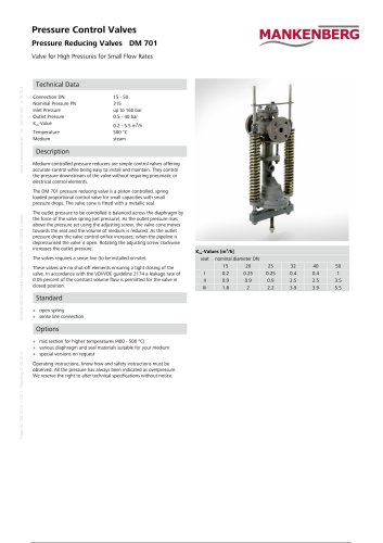
- DM 701: High-pressure valve for steam, robust and long-lasting.
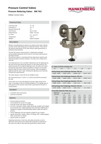
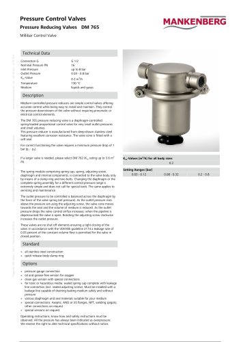
- DM 762, 765: Valves for millibar regulation, precise and available in various configurations.
- Valve Selection: The document outlines a simplified method for selecting the appropriate valve using the Kv-value method, which is sufficient for most applications despite being less precise than DIN IEC 534 standards.
- Kv-Value Calculation: The Kv-value is a flow coefficient representing water flow in m³/h at a differential pressure of 1 bar. The document provides a formula for calculating the Kv-value and recommends adding a 30% margin to determine the Kvs-value for valve selection.
- Flow and Pressure Considerations: Recommendations are provided for maintaining optimal flow velocities in pipelines to minimize pressure loss and noise.
- Valve Sizing: Guidelines for determining the nominal size of valves and pipelines based on flow rates and velocities are included.
The document discusses the selection and operation of pressure control valves, focusing on the adjustment range and material selection based on operational requirements. It highlights that standard adjustment ranges can be exceeded in special cases with lower valve utilization and reduced precision requirements. For example, a pressure reducer with a range of 0.8-2.5 bar can operate satisfactorily at 0.5 bar.
Material Selection:
Materials should be chosen according to operational demands and resistance tables. For toxic or flammable fluids, a closed spring bonnet with a leakage connection may be necessary to safely discharge fluids in case of a control part defect.
Examples and Calculations:
The document provides several examples of selecting appropriate valves based on calculated Kv values, which are adjusted by 30% to determine the minimum Kvs value required. It includes examples for different media such as methanol, water, CO2, and steam, detailing the selection of specific valve types and their characteristics.
Flow and Pressure Calculations:
It explains the calculation of Kv values for both undercritical and overcritical pressure differentials, using formulas for flow coefficients, volumetric flow rates, and pressure differences. The document also covers the determination of nominal diameters to minimize pressure losses and operational noise, recommending specific flow velocities for different pressure ranges.
Valve Selection Guidelines:
Guidelines for selecting valves include ensuring the desired setpoint is near the upper limit of the adjustment range and choosing materials suitable for the application. The document emphasizes the importance of understanding operational behavior to use valves outside catalog-specified application areas in special cases.
Conclusion:
The document concludes with a focus on the know-how of pressure reducing valves, which reduce high, often fluctuating pressures to an adjustable, constant level.
- Type and Size: Choose a valve with a Kvs value at least 30% greater than the calculated Kv value for the maximum flow rate and minimum differential pressure. Consider additional factors for high-viscosity or vaporizing liquids.
- Pressure and Material: The nominal pressure stage should exceed the maximum system pressure without safety margins. Consider temperature effects as per DIN standards.
- Adjustment Range: Select an adjustment range where the desired back pressure is at the upper limit for better control accuracy.
- Elastomers: Choose based on operating temperature and medium requirements. Gases under high pressure can diffuse into elastomers, causing damage upon decompression.
- Liquids: 1 - 5 m/s
- Saturated Steam: 10 - 40 m/s
- Superheated Steam: 15 - 60 m/s
- Gases up to 2 bar: 2 - 10 m/s
- Gases over 2 bar: 5 - 40 m/s
- Control Line: Plan for a control line if the valve is designed for it, ensuring it is connected at least 10 times the nominal width behind the valve.
- System Protection: Install a safety valve to prevent exceeding the maximum operating pressure. Use dirt traps or filters to protect the valve from solid particles.
- Sealing and Isolation: Pressure reducers are not required to be completely leak-proof. For increased seat tightness, special cone seals and larger control surfaces can be used.
- Bypass and Isolation: Plan shut-off devices before and after the valve for maintenance and system closure. A bypass may be necessary for emergency operation.
- Ensure the membrane is filled with water before operation to prevent overheating.
- Do not insulate the valve to avoid overheating and damage to elastomers.
- Use a steam dryer to remove water quickly and prevent damage from wet steam.
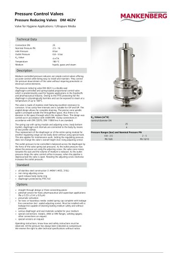
- Connection: DN 15 - 50
- Nominal Pressure: PN 2.5 - 10
- Inlet Pressure: up to 8 bar
- Outlet Pressure: 0.3 - 5 bar
- Kvs Value: 2 - 7 m³/h
- Temperature: 130°C / 180°C
- Medium: Liquids, Gases, Steam
The document details various pressure reducing valves (Druckminderer) from MANKENBERG GmbH, including models DM 506, DM 510-518, DM 512-517, and DM 603. These valves are designed for different pressure ranges and applications, with specifications such as connection sizes (DN 15-150), nominal pressure (PN 16-315), and temperature limits (up to 400°C). The valves are suitable for liquids and gases, with specific models designed for steam.
Materials:
The valves are constructed from materials like CrNiMo-Steel, CrNi-Steel, and optional materials for specific components like membranes and seals, ensuring compatibility with various media.
Options:
Available options include manometer connections, armored valve cones and seats, closed spring hoods for toxic media, and special connections like aseptic, ANSI, or DIN flanges.
Procedures:
The valves operate by balancing the downstream pressure with the force of the valve spring. Adjusting the set screw changes the downstream pressure. These valves are not shut-off devices and may have a leakage rate of 0.05% of the Kvs value in the closed position.
Recommendations:
Installation and operation must follow the provided instructions and safety guidelines. All pressure specifications are given as overpressure, and technical changes are reserved.
Key Data from Tables:
The document includes detailed tables with Kvs values, pressure ranges, and dimensions for each valve model. For example, the DM 603 model has a Kvs value range of 4-160 m3/h and operates at temperatures up to 350°C.
Conclusion:
MANKENBERG's pressure reducing valves offer versatile solutions for controlling pressure in various industrial applications, with customizable options to meet specific requirements.
The document details various pressure reducing valves (Druckminderer) manufactured by MANKENBERG GmbH, including models DM 664, DM 701, DM 762, and DM 765. These valves are designed for different pressure ranges and applications, with specifications such as connection sizes, nominal pressure (PN), inlet and outlet pressure ranges, Kvs values (flow coefficients), and temperature limits.
Materials:
The valves are constructed from high-quality materials like CrNiMo steel for housings and internal parts, with options for different sealing materials such as EPDM, FPM, or PTFE, depending on the medium.
Procedures:
The valves operate by balancing the downstream pressure with the force of the valve spring, allowing for precise pressure regulation without the need for pneumatic or electrical controls. Adjustments can be made via a set screw, and maintenance is simplified by the modular design of the spring module.
Standards and Options:
Standard features include stainless steel construction and pressure relief designs. Optional features include manometer connections, special materials for seals and membranes, and custom connections like aseptic, ANSI, or DIN flanges.
Recommendations:
For optimal performance, it is recommended to use the valves with a properly installed control line. The document also advises adherence to operating instructions and safety guidelines.
Technical Data:
Each valve model has specific technical data, including dimensions, weight, and pressure settings. The document provides detailed tables for these parameters, ensuring users can select the appropriate valve for their application.
Applications:
The valves are suitable for controlling pressures in systems handling liquids and gases, with specific models designed for high-pressure differentials, large flow rates, or millibar regulation.
Connection sizes range from DN 15 to 50 and G 1/2 to 2. The nominal pressure is PN 16, with a shut-off flow rate at least 15% above the operating flow rate. The Kvs value ranges from 4 to 18 m3/h, and the temperature can reach up to 130°C. The valves are suitable for liquids and gases.
Description
Leakage or broken pipes can lead to flooding or severe consequences when dealing with flammable, water-hazardous, or toxic liquids. Pipe rupture shut-off valves are used at the system's entry point to prevent such incidents. The RS 659 is a piston-controlled, spring-loaded valve made entirely of CrNiMo steel. It operates by closing when the flow rate exceeds a preset limit, ensuring a tight seal. The closing speed can be adjusted, and the valve can be reopened after resolving the issue.
Materials
The valve components, including the housing, spring cover, internal parts, and adjustment screw, are made of CrNiMo steel. The valve seal can be NBR or CrNiMo steel, and the spring is made of CrNi steel.
Dimensions
Dimensions vary based on nominal width, with specific measurements provided for each size. Special designs are available upon request.
Vacuum Breakers and Control Valves
Vacuum breakers protect systems from underpressure by opening when the internal pressure drops below a set differential pressure. They are available in various types, with options for different materials and configurations. Regular maintenance is required to ensure functionality.
Safety Valves
Safety valves, such as the SV 29, are spring-loaded and suitable for liquids, gases, and steam. They are available in normal and full-lift versions, with specific pressure and temperature ratings.
General Notes
All pressure specifications are given as overpressure. Technical changes are reserved, and safety instructions must be followed.
- Normal Safety Valves: These open in a proportional phase up to a 10% pressure increase, followed by a full-lift phase for high mass flow, ensuring steady operation, especially with liquids.
- Proportional Safety Valves: These open steadily with pressure increase, suitable for small mass flows and minimizing medium loss.
- Full-Lift Safety Valves: These open rapidly within a 5% pressure increase, ideal for sudden large mass flows or rapid pressure increases, primarily used for steam and gas pressure relief.
The document provides detailed specifications for safety valves SV 4, SV 40, SV 6, and SV 60, including connection sizes (DN 15-150), nominal pressure (PN 16-40), response pressure (0.5-40 bar), and temperature limits (up to 200°C). The valves are suitable for liquids, gases, and steam.
Valve Descriptions:
Safety valves are critical for preventing excessive pressure in containers and pipelines. SV 4 and SV 40 are spring-loaded, component-tested normal and proportional safety valves with flange connections. SV 6 and SV 60 are full-lift safety valves designed for rapid opening in response to pressure increases.
Operating Principles:
Normal safety valves open proportionally up to a 10% pressure increase, followed by a full-lift phase. Proportional safety valves open steadily with pressure increase, suitable for small mass flows. Full-lift valves open rapidly within a 5% pressure increase, ideal for sudden large mass flows.
Options and Customizations:
Custom versions are available for temperatures up to 300°C. Various configurations include options with or without venting and gas-tight caps.
Materials:
The document lists materials used for different valve components, including various grades of stainless steel and other alloys, ensuring durability and performance under specified conditions.
Dimensions and Weights:
Detailed dimensions and weights for each valve type and size are provided, with specific configurations for stainless steel versions available upon request.
Flow Rates:
The document includes tables detailing flow rates for steam, air, and water across different valve sizes and pressures, highlighting the capacity and efficiency of each valve type.
Pilot-Controlled Valves:
Information on pilot-controlled pressure reducing and overflow valves for water, designed for high throughput and specific for drinking water applications, is also included. These valves feature adjustable closing, opening, and reaction speeds.
The document provides technical specifications and operational details for various pilot-operated control valves, specifically the RP 814, RP 815, RP 818, RP 820, RP 824, and RP 825 models. These valves are designed to regulate pressure in pipelines without the need for pneumatic or electrical control components.
Specifications
The valves are constructed with a main valve and a pilot valve, with materials including steel and CrNiMo steel for durability. They operate effectively at temperatures up to 130°C and are suitable for both liquids and gases. The valves are not designed to be shut-off devices and may have a leakage rate of 0.05% of the Kvs value as per VDI/VDE guideline 2174.
Operational Details
The valves function by maintaining a pressure differential to open or close the main valve. A pre-tensioned spring keeps the main valve closed when the pipeline is depressurized. The pilot valve adjusts based on the set pressure, allowing the main valve to open or close accordingly. The system includes throttles to optimize control behavior and a bypass with a check valve for rapid closure.
Options and Customizations
Options include electric limit switches and special designs upon request. All pressure specifications are given as overpressure, and technical changes are reserved.
Dimensions and Weights
The document provides detailed dimensions and weights for each valve type across various nominal widths (DN). For example, the RP 814 model ranges from DN 100 to DN 800, with corresponding Kvs values and weights specified.
Installation and Safety
Installation requires external impulse lines, and adherence to the provided operating instructions, know-how, and safety guidelines is mandatory. The valves are internally piped, and the impulse lines must be installed on-site.
Conclusion
These pilot-operated control valves offer precise pressure regulation with easy installation and maintenance, suitable for a range of industrial applications.
The document provides detailed specifications for various air release and vacuum valves, including dimensions, pressure ratings, and materials. The valves are designed for different applications, such as continuous operation and high air flow rates. Key specifications include:
- Nominal diameters (DN) ranging from 32/15 to 100/50.
- Pressure ratings (PN) up to 40 bar.
- Temperature tolerance up to 200°C.
- Materials include spheroidal graphite iron and stainless steel for corrosion resistance.
The document outlines installation and operational procedures for air release and vacuum valves. Key points include:
- Valves should be installed at high points in pipelines and tanks to effectively manage air and gas release.
- Ensure the installation site allows for smooth airflow and prevents water hammer effects.
- Regular maintenance and cleaning are necessary, especially in systems with dirty or foamy media.
The document emphasizes the importance of selecting the correct valve type and size based on operational pressure and air flow requirements. Recommendations include:
- Using check valves to prevent unwanted air intake.
- Choosing elastomers and coatings suitable for the specific media being handled.
- Consulting technical support for extreme operating conditions.
The document includes tables detailing:
- Valve dimensions and weights for different pressure ratings and nominal diameters.
- Air flow rates at various differential pressures, highlighting the capacity of each valve type.
- Material specifications for different temperature ranges.
Important considerations include:
- Ensuring the working pressure range accommodates the maximum operating pressure to prevent valve malfunction.
- Properly sizing valves to avoid over-dimensioning, which can lead to operational inefficiencies.
- Implementing safety measures to protect against pressure surges and water hammer.
This document provides technical specifications, procedures, and safety instructions for various air release and intake valves designed for industrial applications. These valves are used to release air or gases from systems without external energy and can also function as air intakes when systems are drained.
Specifications
The document details several models of valves, including EB 1.12, EB 1.32, EB 1.20, and EB 1.48, each with specific technical data such as connection sizes, nominal pressure, working pressure, throughput, temperature, and suitable media. For instance, the EB 1.12 and EB 1.32 models are compact, float-controlled devices made from stainless steel, suitable for water treatment and other applications.
Materials and Construction
The valves are constructed from high-quality materials like CrNiMo steel, ensuring excellent corrosion resistance. The document specifies different sealing materials and options for customization, such as ozone-resistant versions and special coatings for aggressive liquids.
Performance and Limitations
Throughput values are provided for fully open valves under standard conditions (0°C and 1013 mbar). It is noted that continuous operation throughput is approximately 30% lower. The document advises against oversizing valves, as this can lead to reduced performance.
Options and Customizations
Various options are available, including different sealing materials, check valves to prevent air intake, and special connections like aseptic, ANSI, or DIN flanges. Custom designs are available upon request.
Installation and Maintenance
The valves are designed for easy installation and maintenance, with quick-release housings and minimal need for special tools. The document emphasizes the importance of following the provided instructions and safety guidelines.
Conclusion
The document concludes with a reminder that all pressure specifications are given as overpressure and that technical changes may occur. It also provides contact information for further inquiries and support.
The document describes air release and vacuum valves made from CrNiMo steel, known for their corrosion resistance, lightweight, and compact design. These valves are suitable for all liquids and are available in special materials like seawater-resistant stainless steels. They are designed for long life and easy maintenance with a clamp system.
Technical Data:
- Nominal Diameter (DN): 25 - 100
- Nominal Pressure (PN): 16
- Operating Pressure: DN 25 - 50 up to 12 bar, DN 65 - 100 up to 13 bar
- Flow Rate: 1935 Nm³/h
- Temperature: 130°C
Functionality:
These valves automatically release or admit air or gases from containers or pipelines. They are float-controlled, closing with rising liquid levels and opening when levels fall. The valves are designed to prevent vacuum damage by opening during sudden vacuum conditions.
Types of Valves:
- Start-up Air Release Valves: Used during system start-up or filling, they have a large seat diameter for quick air release at low pressures.
- Continuous Air Release Valves: Used to expel air during operation, equipped with a lever mechanism to function at varying pressures.
- Combined Air Release and Vacuum Valves: These combine features of start-up and continuous valves, with large and small seats for different operational phases.
Materials and Coatings:
Standard versions are suitable for water up to 80°C, with options for higher temperatures and specific media like hydrocarbons and chlorides. Special coatings and elastomers are available for aggressive media.
Installation and Maintenance:
Valves should be installed at high points in pipelines and containers, avoiding locations like standpipes. Regular maintenance is required, especially for liquids with deposits. Safety instructions and operating manuals must be followed.
Options and Customizations:
Valves can be customized with different sealing materials, coatings, and special connections like aseptic or ANSI flanges. Custom designs are available upon request.
Performance Data:
Flow rates and pressure drops are provided for various nominal diameters and pressures, ensuring the correct selection for specific applications.
This document provides technical specifications and descriptions for various models of float-controlled condensate traps manufactured by MANKENBERG GmbH. These devices are designed to automatically discharge condensate without steam or gas losses, operating efficiently under varying pressure conditions without the need for additional energy.
KA 2K Condensate Trap
- Specifically designed for cold condensates.
- Materials: Housing, seat, cone, and float made of CrNiMo steel; seals made of FPM.
- Installation requires a steady slope for condensate flow and may need a pendulum line for water lock prevention.
- Dimensions and weights vary based on nominal width.
KA 2X Condensate Trap
- Universal device for higher throughput, suitable for aggressive condensates and food industry applications.
- Materials: Entirely made of CrNiMo steel with metallic sealing cone.
- Features a quick-release housing and optional air vent.
- Handles pressures up to 13 bar and temperatures up to 190°C.
KA 3 Condensate Trap
- Universal device with thermal venting, suitable for aggressive condensates and high purity requirements.
- Materials: Made of CrNiMo steel with options for polished surfaces.
- Features include a thermal internal vent and quick-release housing.
- Handles pressures up to 12 bar and temperatures up to 190°C.
KA Axomat Condensate Trap
- Universal device made of cast material, suitable for systems with fluctuating pressures.
- Features a variable cone lift and options for high-temperature applications.
- Materials: Cast iron or steel, with CrNiMo steel components.
- Handles pressures up to 40 bar and temperatures up to 200°C.
KA Niagara Condensate Trap
- Robust and powerful device for high throughput applications.
- Materials: Spheroidal graphite iron or steel, with CrNiMo steel components.
- Features include various venting options and a hand air valve.
- Handles pressures up to 40 bar and temperatures up to 200°C.
General Notes
- All pressure specifications are given as overpressure.
- Technical changes are reserved, and special versions are available upon request.
- Installation and operation must adhere to provided guidelines and safety instructions.
The document details various types of float valves used for regulating liquid levels in tanks. These valves are made from CrNiMo-Steel, known for its excellent corrosion resistance. The valves are designed for different pressure ranges and nominal widths, with specific dimensions and weights provided for each type.
Materials:
The main materials used include CrNiMo-Steel for the housing, cone, seat, and float. The valve seals are made from EPDM for temperatures up to 130°C and metallic seals for temperatures up to 300°C.
Technical Data:
Connection sizes range from G 3/8A to 1 1/2A, with a nominal pressure of PN 16 and working pressures from 0 to 8 bar. The Kvs values, indicating flow capacity, range from 0.5 to 82 m3/h, and the valves can handle temperatures up to 300°C.
Valve Types and Applications:
NV 94 and NV 98 are specific models designed for horizontal or vertical installation in tanks. NV 94 is suitable for both inflow and outflow applications, while NV 98 is primarily for inflow with the outlet directed downwards. The document also describes the NV 55 series, which includes variations with relief and double seats for different pressure and flow requirements.
Installation and Operation:
Float valves are installed in tanks to automatically regulate liquid levels without auxiliary energy. The float directly controls the valve via a lever, adjusting the flow based on the liquid level. The document emphasizes the importance of selecting the correct valve type and size based on the maximum operating pressure and flow requirements.
Options and Customizations:
Different sealing materials are available to suit various media, and custom designs can be requested. The document advises specifying the working pressure range when ordering.
Maintenance and Safety:
Regular cleaning and maintenance are crucial, especially for valves used infrequently or in environments with particulate matter. The document highlights the need for oil- and silicone-free devices in certain applications and advises consulting a technician for extreme operating conditions.
Additional Features:
The document includes information on overfill protection devices approved for flammable liquids and provides guidelines for ensuring seat tightness and adjusting fill levels.
- Connection Sizes: DN 15 - 400
- Nominal Pressure: PN 10 - 40
- Operating Pressure: 0 - 16 bar
- Kvs Value: 2.6 - 1800 m³/h
- Temperature: Up to 130°C
- Medium: Liquids
- NV 55: Double-seated valve with container connection flange for vertical flow, equipped with a soft seal for tight closure.
- NV 55e: Single-seated, relieved valve with vertical flow, featuring a soft-sealing cone.
- NV 56: Double-seated valve with high flow capacity, suitable for vertical flow.
- NV 67e: Single-seated, relieved valve made from deep-drawn stainless steel, known for its corrosion resistance.
- Housing: Options include grey cast iron, spheroidal graphite iron, cast steel, and CrNiMo steel.
- Sealing: EPDM
- Components: Various components are available in CrNiMo steel for enhanced durability.
- Rubber or plastic coatings for aggressive media.
- Different sealing materials to suit specific media.
- Special designs available upon request.
- Connection: DN 15 - 150
- Nominal Pressure: PN 16
- Operating Pressure: 0 - 16 bar
- Kvs Value: 4 - 160 m³/h
- Temperature: 130 °C
- Medium: Liquids
Float valves automatically regulate liquid levels in closed or open (non-pressurized) containers without auxiliary energy. A float detects the liquid level and directly controls the valve via a lever. A change in level immediately alters the flow rate. NV 16e is a pipeline valve for horizontal or vertical flow, with a soft-sealing cone. The valves are equipped with a float rod on which a float with an inner tube is mounted (Mantel float SR 8). The liquid level can be continuously adjusted by moving the float on the float rod.
For float valves with a float rod: If the liquid level is lower than the float lever - meaning the float points downwards - a guide for the float rod must be provided on-site.
When making inquiries and orders, please specify the following additional letters:
- Z = Inflow. Valve closes when the float rises
- A = Outflow. Valve closes when the float falls
- w = Horizontal flow
- o = Upward flow
- u = Downward flow
- Float rod 1m length made of CrNiMo steel
- Mantel float with inner tube SR 8 made of CrNiMo steel
- Special length float rod
- Rubber or plastic coating for aggressive media
- Different sealing materials suitable for your medium
- Special designs on request
- Housing: PN 16 up to DN 25 gray cast iron, from DN 40 ductile iron
- PN 25/40 cast steel
- Cone and seat: gray cast iron, Cr steel
- Piston and spindle: Cr steel, optionally CrNiMo steel
- Valve seal: EPDM
- Rod: galvanized steel or steel
- Float rod: CrNiMo steel
- Float: CrNiMo steel
Dimensions and weights are provided for various nominal widths (DN) and pressure ratings (PN). Specific measurements and weights are detailed for each DN size.
All pressure specifications are given as overpressure. Technical changes are reserved.
- Flag Indicators: Suitable for liquids, gases, and two-phase mixtures. They come with or without return springs and can be installed in various orientations depending on the presence of a spring.
- Rotary Wheel Indicators: Designed for small flow rates of liquids, these can be installed horizontally or vertically.
- Ball Indicators: Used for both liquids and gases, with installation typically vertical, allowing flow from bottom to top.
- Housings are made from materials like grey cast iron, C 22.8 / St 37-2, and CrNiMo steel, depending on pressure requirements.
- Seals are made from Nova Universal material, with optional borosilicate glass for higher temperature resistance.
- Internal components are typically made from CrNiMo steel.
- Devices with return springs can be installed in any orientation, while those without springs have specific orientation requirements.
- Flow indicators with a flag for changing flow directions have specific installation instructions to ensure proper operation.
- Operating temperatures range from 80°C to 280°C, depending on the model and materials used.
- Pressure ratings vary, with PN 16 to PN 40 being common across different models.
- Flow indicators are available in various sizes, with specific dimensions and weights provided for each type.
- Different sealing materials and glass types are available to suit various media.
- Special designs and connections, such as aseptic, ANSI, or DIN flanges, can be requested.
Anschluss: DN 15 - 150
Nominal Pressure: PN 16
Kvs Value: 4 - 160 m3/h
Temperature: 200 °C
Medium: Liquids, Gases, and Steam
The control valve, also known as a regulating valve, is often the actuator in a control loop. It functions as a throttling device to set the desired flow rate in a pipeline. The AV 50.2 is a through valve with an electromechanical drive, used for control and regulation tasks in process engineering, industrial plants, and power supply technology. Its special design ensures a consistent control characteristic.
» Electric actuator (230VAC, 50HZ, 1 Phase)
» Housing made of spheroidal graphite iron
» Metal sealing
» Robust
» Proven valve housing design and drive technology
» Made in Germany – 25-year spare parts guarantee
» Durability
» Individual consultation
Housing: GGG 40.3 / Spheroidal graphite iron
Parabolic cone: 1.4104
Valve spindle: 1.4104
Seat: 1.4305
Packing: Graphite
Dimensions and weights are provided for various nominal widths and pressure ranges, with specific measurements for each.
Includes options for membrane expansion vessels and float designs, with specifications for materials and dimensions.
Connection: G 1/2
Nominal Pressure: PN 10
Working Pressure: 0 - 10 bar
Temperature: 130 °C
Medium: Liquids
The AKM 200 serves as a pressure relief device in smaller fluid systems, preventing unacceptable pressure increases due to thermal expansion. It operates autonomously after initial gas filling without auxiliary energy, recommended for use with inert gases for flammable liquids.
» Stainless steel housing
» FPM housing seal and membrane
» Quick-release housing closure
» Manometer connection
Options include different materials for membranes and seals, hand air valve for venting, and adjustable inert gas supply connection.
Housing: CrNiMo steel
Housing seal: FPM
Membrane: FPM
Filling valves: Nickel-plated brass
Specific dimensions and weights are provided for various components and configurations.
Specifications for float dimensions, wall thickness, pressure ratings, and buoyancy are detailed for different models and applications.
Catalog excerpts

Pressure Control Valves Bleeding and Venting Valves Steam Traps Float Valves Pipeline Ancillaries Control Valves Costumised Solutions Zertifikarte I Inlornutionen cRtl* ' Certificates / Informations
Open the catalog to page 2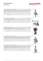
Druckregelventile Druckminderer www.mankenberg.de | Tel. +49 (0) 451 - 8 79 75 0 Ventil für Hygieneanwendung / hochreine Medien DM 152 Eckventil geeignet für kleinen bis mittleren Durchsatz | einsetzbar für Flüssigkeiten, Gase, Dampf | komplett CrNiMo-Stahl tiefgezogen | totraumarm, elektropolierbar, korrosionsbeständig, leicht und kompakt, Regler ohne Hilfsenergie | bei CIP/SIP-Reinigungsverfahren Reduzierung der Reinigungsintervalle, geringerer Energieaufwand durch dünne Wandstärke, wartungsfreundlich durch Schellensystem, pneumatische Ansteuerung möglich DN 15 - 50 PN 2,5 - 10 p2 0,3 - 5 bar...
Open the catalog to page 3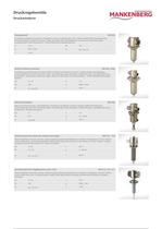
Druckregelventile Druckminderer www.mankenberg.de | Tel. +49 (0) 451 - 8 79 75 0 Standardventil DM 502 aus Edelstahl und Messing | einsetzbar für Flüssigkeiten und Gase, Standardventil für CO2 | Gehäuse CrNiMo-Stahl, Innenteile Messing | korrosionsbeständig, sehr leicht und kompakt, Regler ohne Hilfsenergie | viele Regelbereiche, pneumatische Ansteuerung möglich, wartungsfreundlich durch Schellensystem – höchste Effektivität bei kompakter Bauweise G 1/2 - 2 PN 100 p2 0,02 - 16 bar Kvs 0,6 - 4,2 m3/h T 130 °C Ventil für kleinen Durchsatz DM 505, 505Z verschiedene Durchsatzleistungen (Kvs-Werte)...
Open the catalog to page 4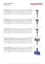
Druckregelventile Druckminderer www.mankenberg.de | Tel. +49 (0) 451 - 8 79 75 0 Standard Gussventil DM 603 bis 350 °C, Stahl/ Edelstahl, Edelstahl-Membran-Gehäuse, Höchstzahl an verschiedenen Regelbereichen | einsetzbar für Flüssigkeiten, Gase, Dampf | Gehäuse GGG-40, GS-C25, CrNiMo-Stahl DN 15 - 150 PN 16 - 40 p2 0,02 - 10 bar Kvs 4 - 160 m3/h T bis 350 °C Standard Gussventil DM 604 bis 250 °C, Stahl/ Edelstahl, Edelstahl-Membran-Gehäuse, Höchstzahl an verschiedenen Regelbereichen | einsetzbar für Flüssigkeiten, Gase, Dampf | Gehäuse GGG-40, GS-C25, CrNiMo-Stahl 15 - 150 PN 16 - 40 p2 0,02...
Open the catalog to page 5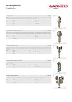
Druckregelventile Druckminderer www.mankenberg.de | Tel. +49 (0) 451 - 8 79 75 0 Universalventil DM 652 entlastet, verschiedenste Anschlüsse und Sonderausführungen verfügbar | einsetzbar für Flüssigkeiten, Gase, Dampf | komplett CrNiMo-Stahl tiefgezogen | höchste Regelgenauigkeit, hohe Durchflüsse, Vielzahl an Regelbereichen | pneumatische Ansteuerung möglich, Variantenvielfalt bei überzeugender Qualität für Ihre individuelle Anwendung, wartungsfreundlich durch Schellensystem DN 15 - 50 G 1/2 - 2 PN 40 p1 40 bar p2 0,02 - 12 Kvs 5 - 22 m3/h T 190 °C Universalventil für mittleren Durchsatz DM...
Open the catalog to page 6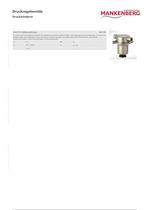
Druckregelventile Druckminderer Blatt Nr. DM/1.0.70.5 - Stand 01.01.1970 MANKENBERG GmbH | Spenglerstraße 99 | D-23556 Lübeck www.mankenberg.de | Tel. +49 (0) 451 - 8 79 75 0 Ventil für Millibarregelungen DM 765 für kleinen Durchsatz, kompakt | einsetzbar für Flüssigkeiten und Gase | komplett CrNiMo- Stahl tiefgezogen | korrosionsbeständig, sehr leicht und kompakt, Regler ohne Hilfsenergie | lange Lebensdauer, handliche Montage, wartungsfreundlich durch Schellensystem, pneumatische Ansteuerung möglich, Vielfalt an Ausführungen und Anschlussvarianten G 1/2 PN 16 p2 0,03 - 0,8 bar Kvs 0,2 m3/h...
Open the catalog to page 7
Auslegung von Druckregelventilen www.mankenberg.de | Tel. +49 (0) 451 - 8 79 75 0 Anleitung Auslegung und Auswahl von Druckregelventilen ist keine nur von einigen Experten beherrschte Geheimwissenschaft. Die hier vorgestellte Vorgehensweise ermöglicht es, mit relativ geringem Aufwand das für einen bestimmten Anwendungsfall geeignete Ventil auszuwählen. Die auf der sogenannten Kv-Wert-Methode basierenden Berechnungswege sind, verglichen mit den sehr akkuraten der DIN IEC 534, sehr vereinfacht. Sie führen aber zu für unsere Zwecke hinreichend genauen Ergebnissen. Der Kv - Wert ist ein Durchflusskoeffizient,...
Open the catalog to page 8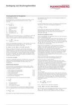
Auslegung von Druckregelventilen www.mankenberg.de | Tel. +49 (0) 451 - 8 79 75 0 Druckregelventile für Flüssigkeiten Ermittlung des Kv-Wertes Zur Auslegung bzw. vor Auswahl eines Ventils wird zunächst aus den Betriebsdaten, bei denen das Ventil arbeiten soll, der Kv - Wert errechnet. In unserem Beispiel hätten wir dann in der Rohrleitung DN 40 bei einem Durchsatz von 7m³/h eine Strömungsgeschwindigkeit von Kv Q p1 p2 Δp Durchflusskoeffizient Volumendurchfluss Dichte Eintrittsdruck (abs.) Austrittsdruck (abs.) Druckdifferenz (p1 - p2) m³/h m³ kg/m³ bar bar bar Die Nennweite des Regelventils darf...
Open the catalog to page 9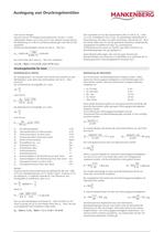
www.mankenberg.de | Tel. +49 (0) 451 - 8 79 75 0 Auslegung von Druckregelventilen Und noch ein Beispiel: Gesucht wird ein CIP-fähiges Druckminderventil, mit dem 1-3 l/min vollentsalztes Wasser von 2-4 bar auf 0,7 bar reduziert werden können. Die Rohrleitung ist in DN 25 mit Klemmverbindungen nach DIN 32 676 ausgeführt. Anhand der Betriebsdaten rechnen wir den Kv - Wert aus Wir entscheiden uns für den Druckminderer DM 152 DN 25, Kvs - Wert 3,5 m³/h, Einstellbereich 0,8-2,5 bar, ein polierfähiges Edelstahlventil in Eckausführung. Wir haben uns dafür entschieden, obwohl der Kvs - Wert des Ventils...
Open the catalog to page 10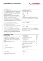
Auslegung von Druckregelventilen www.mankenberg.de | Tel. +49 (0) 451 - 8 79 75 0 Auswahl eines geeigneten Ventils Unsere Auswahltabellen und Datenblätter führen Sie zu den technischen Daten der MANKENBERG-Ventile. Der Kvs - Wert des ausgewählten Ventils sollte dem errechneten und mit den erforderlichen Zuschlägen versehenen Kv - Wert entsprechen. Die meisten Ventile arbeiten am besten im Bereich von 10 bis 70 % ihres Kvs - Wertes, kleine nicht enlastete Ventile – wie z.B. die Druckminderer DM 502, 505, 506, 510, 762 und 765 – arbeiten auch bei kleinsten Durchsätzen noch zufriedenstellend. Wählen...
Open the catalog to page 11All MANKENBERG GmbH catalogs and technical brochures
 Float Valves NV 98
6 Pages
 UV 5.5
2 Pages
 Short Catalogue
68 Pages