


- Company
- Products
- Catalogs
- News & Trends
- Exhibitions
Micro Dyne | Motors Testing System

Micro Dyne | Motors Testing System
- Torque range: 2.0 mN·m to 4.0 mN·m
- Speed: Up to 100,000 rpm
- Power: 4 W
- Low inertia and complete out-of-the-box system
- Includes hysteresis dynamometer, motor fixture, dedicated electronics, and comprehensive software
- Dynamometer: Utilizes a hysteresis braking system for torque measurement independent of speed.
- Electronic Unit: Features DSP technology for data acquisition and control, with USB connectivity.
- Motor Fixture: Adjustable XYZ stage for motors 5 mm to 30 mm in diameter.
- Software: M-TEST 7 for performance measurement and data analysis.
- Dynamometer: Offers two torque configurations (2.0 mN·m and 4.0 mN·m), with a maximum speed of 100,000 rpm.
- Environmental Requirements: Operating temperature 0 °C to +70 °C, relative humidity < 60%.
- Electrical Unit: Voltage requirements 85 – 264 V AC, power accuracy 0.4% of VA range.
- Speed Measurement: Uses a reflective fiber optic speed pickup for rpm readings.
- Torque Measurement: Employs a hysteresis brake to measure reaction torque.
- Dynamometer: Weight 4.2 kg (9.3 lb)
- Electronic Unit: Weight 1.5 kg (3.2 lb)
Catalog excerpts

MICRO DYNE MICRO DYNE MOTOR TESTING SYSTEM FEATURES ▪ designed specifically for miniature and micro motors ▪ Torque: Easily convertible from 2.0 mN·m to 4.0 mN·m (0.28 oz·in to 0.57 oz·in) ▪ Speed: up to 100,000 rpm ▪ Power: 4 W ▪ Low inertia ▪ Sold as a complete, out-of-the-box motor testing system. Components include: ▪ Hysteresis Dynamometer: provides precise torque loading independent of shaft speed ▪ Motor Fixture: accommodates motors from 5 mm to 30 mm in diameter. ▪ Dedicated Electronics: all-in-one dynamometer controller, DC wattmeter, power relay and USB interface Fig. 1: Micro Dyne Motor Testing System ▪ Comprehensive Motor Testing Software ▪ Easy-to-use calibration software ▪ All necessary connection cables ▪ Calibration weights: 5 g and 10 g DESCRIPTION With over 50 years’ experience in dynamometer design and torque measurement, Magtrol has revolutionized the industry. Magtrol’s new Micro Dyne, capable of measuring extremely low torques (2.0 mN·m can be resolved to 0.0004 mN·m), is designed exclusively for testing miniature and micro (low-torque) motors. For the utmost convenience, the Micro Dyne is packaged as a COMPLETE MOTOR TESTING SYSTEM. Everything that is needed to accurately and efficiently test miniature motors and micro motors is included with the purchase of a Magtrol Micro Dyne. The only component that needs to be supplied by the customer is a laptop or desktop personal computer and motor power supply. Motor Characteristics Measured/Calculated: ▪ Torque ▪ Speed ▪ Amps ▪ Volts ▪ Horsepower ▪ Efficiency ▪ Input Watts ▪ Output Watts © 2020 MAGTROL | Due to continual product development, Magtrol reserves the right to modify specifications with
Open the catalog to page 1
MICRO DYNE APPLICATIONS Magtrol motor test systems can be found in test labs, at inspection stations, and on the manufacturing floors of most of the world’s leading motor manufacturers. The Micro Dyne system is used exclusively for closed-loop testing of miniature motors and micro motors used in low-torque/high-speed applications. Motor sub-types include, but are not limited to, the following: These mini/micro motors are used in a diverse range of industries and products, including: ▪ Medical and laboratory equipment ▪ Robotics and automation ▪ Toys ▪ Handheld communication devices ▪ Brushed...
Open the catalog to page 2
MICRO DYNE SYSTEM CONFIGURATION shipping bolt knob Electonic Unit functions as a: • Dynamometer Controller • DC Wattmeter • Power Relay • USB Interface dynamometer shaft motor under test motor clamping strap (with knurled cam grip) Motor Fixture motor power IN terminals motor electrical connection motor fixture adjustment knobs (height, width, depth) motor power OUT terminals voltage sense terminals leveling knobs BLOCK DIAGRAM Motor Under Test Slotted Disc motor power speed signal (via fiber optic speed pickup) PC with M-TEST 7 and calibration software torque signal brake power Power Supply...
Open the catalog to page 3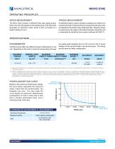
MICRO DYNE OPERATING PRINCIPLES SPEED MEASUREMENT TORQUE MEASUREMENT The Micro Dyne contains a reflective fiber optic speed pickup. Each rotor slot that passes by the sensing end of the fiber optic generates an electronic pulse, which is then converted to a speed reading (in rpm). A hysteresis brake is used to develop a resistance to rotation of a mechanical shaft. A torsional force is produced by the test motor and applied to the brake’s rotor-shaft assembly. Reaction torque is measured by the angle of the brake pendulum assembly and is interpreted by the Micro Dyne system software (M-TEST 7)....
Open the catalog to page 4
MICRO DYNE SPECIFICATIONS MOTOR FIXTURE ELECTRICAL UNIT MOTOR ACOMMODATION GENERAL ELECTRICAL CHARACTERISTICS Fuse (5 × 20 mm) Motor Diameter Power Requirements Voltage Requirements Motor Length Motor Shaft Diameter Maximum Load ENVIRONMENT Operating Temperature Relative Humidity Controllable Motion Current Input (isolated) Voltage Input (isolated) Travel per Knob Revolution Conversion Rate Power Accuracy Isolation, channel-to-channel MOTOR CLAMPING BAND 3 AXIS MOTOR FIXTURE ADJUSTABLE ±5mm ON ALL AXES BINDING POST FOR MOTOR POWER CONNECTION WIRE BUNDLE LEVELING HARWARE DYNAMOMETER SHAFT *Y-AXIS:...
Open the catalog to page 5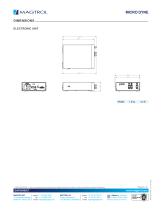
MICRO DYNE DIMENSIONS ELECTRONIC UNIT 264 245 THIRD ANGLE PROJECTION THIS DRAWING AND SPECIFICATION CONTAINS PROPRIETARY INFORMATION TO MAGTROL INC. ANY DISCLOSURE OR REPRODUCTION OF THIS DOCUMENT WITHOUT WRITTEN AUTHORIZATION FROM MAGTROL INC. IS EXPRESSLY PROHIBITED 3 DIMENSIONAL VIEW SCALE 1 : 4 UNLESS OTHERWISE SPECIFIED: DIMENSIONS ARE IN MILLIMETERS, DIAMETERS CONCENTRIC: 0.08 TIR, FACES PERPENDICULAR: 0.08 INTERPRETATION PER ASME Y14.5M-1994 REMOVE ALL BURRS AND BREAK SHARP EDGES 0.13/0.25 X 45°, ALL INSIDE CORNERS TO BE R 0.5 MAX. TOLERANCES: ± 0.4 X.XX ± 0.13 X ANG. ± 1° X.X ± 0.25 SURFACE...
Open the catalog to page 6All MAGTROL catalogs and technical brochures
 4 QUADRANT
2 Pages
 ZM Series
5 Pages
 SK-01 Series
3 Pages
 HB/MHB Series | Hysteresis Brake
12 Pages
 MODEL 7500 | Power Analyzer
4 Pages
 TSB | Torque & Speed Box
2 Pages
 MODEL 3411 | Torque Display
4 Pages
 MD-01 | Transducer
2 Pages
 KG-06 | Extensometer
2 Pages
 SG-01 | Cable Sensor
2 Pages
 AMF Series
3 Pages
 LE Series | Load Measuring Pins
10 Pages
 WB23 & WB27
7 Pages
 HPM/HPMC Series Permanent
3 Pages
 Model 5200
1 Page
 5211
52111 Page
 5251-2
1 Page
 Custom motor test system
1 Page
 Remote Swtich Box
1 Page
 Coupling Guards
1 Page
 SBB 14
3 Pages
 Free-Run Speed Sensor
2 Pages
 FMF SERIES
5 Pages
 LB/MLB SERIES
4 Pages
 ZS Series
7 Pages
 RSB
RSB1 Page
 PC-150
2 Pages
 PCB
PCB1 Page


Archived catalogs
 CST 113
4 Pages
 Product Overview
6 Pages
 Brakes and Clutches
6 Pages
 Torque-Speed-Power
6 Pages
 WB/PB 15
8 Pages
 WB/PB 65
8 Pages


- Display module
- DC power supply
- AC/DC power supply
- MAGTROL load cell
- LCD display panel
- Measuring device
- Industrial display panel
- MAGTROL test bench
- MAGTROL tension/compression load cell
- Single-pole switch
- MAGTROL steel load cell
- Windows software
- CE power supply
- MAGTROL strain gauge load cell
- Single-output power supply
- Digital indicator
- MAGTROL stainless steel load cell
- Power supply for industrial applications
- Flexible coupling