Group: AMETEK

Catalog excerpts
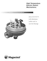
High Temperature Electric Switch Mechanisms Installation and Operating Manual Series F, R, 8 & 9 with aluminum, carbon steel, or cast iron housings
Open the catalog to page 1
Read this Manual Before Installing This manual provides information on Electric Switch Mechanisms. It is important that all instructions are read carefully and followed in sequence. Detailed instructions are included in the Installation section of this manual. Notice of Copyright and Limitations Magnetrol and Magnetrol logotype & are registered trademarks of Magnetrol International. Conventions Used in this Manual Certain conventions are used in this manual to convey specific types of information. General technical material, support data, and safety information are presented in narrative...
Open the catalog to page 2
Reference Information Principle of Operation Figures 1 & 2 illustrate the simple, reliable operating principle of a float level switch. Switching action is obtained through the use of a magnetic sleeve and a float , displacer or flow sensing element and a switching mechanism . These two basic component assemblies are separated by a non-magnetic, pressure retaining enclosing tube . The switch and magnet are assembled to a mechanism with a swinging arm which operates on precision stainless steel pivots. As level of a liquid in a vessel rises (Figure 1), the float rides on the liquid surface...
Open the catalog to page 4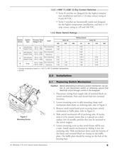
• Series R switches are designed for the highest temperature installations and have a 1.0 amp contact rating at 8 and 30 VDC. • Series 9 switches are hermetically sealed and designed for the highest temperature installations, and have a 1.0 amp contact rating at 120 and 240 VAC. 1.3.3 Basic Switch Ratings Rating (amps) Switch Series Switch Type Process Temp Range F (C) Hermetically Sealed Snap Hermetically Sealed Snap Hermetically Sealed Snap Snap Process temperature based on +100° F (+38° C) ambient temperature 28 VDC Replacing Switch Mechanism Caution: Before attempting to remove a switch...
Open the catalog to page 5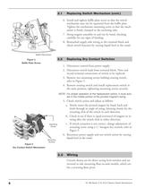
Replacing Switch Mechanism (cont.) 6. Install and tighten baffle plate screw so that the switch mechanism may not be separated from the baffle plate. Tighten the mechanism mounting screw so that the mechanism is firmly clamped to the enclosing tube. 7. Swing magnet assembly in and out by hand, checking carefully for any signs of binding. 8. Reattached supply-side wiring to the terminal block and check switch function by varying liquid level in the vessel. Baffle Plate Screw Replacing Dry Contact Switches Baffle Plate Screw 1. Disconnect control from power supply. 2. Disconnect switch leads...
Open the catalog to page 6
Close on Low Level (NC) Common (C) Close on High Level (NO) Line Internal Circuit 1. Rising level closes contacts 5 & 6, see Figure 6. 2. Falling level closes contacts 4 & 5. 3. Wiring Diagram is reversed (high level actuation becomes low level actuation, etc.) when this switch mechanism is used on side mounted float switches employing a reversing pivot (Models B40, T52, T62, T63, etc.). Figure 6 Single Float with One Switch Upper stage operates upper switch mechanism Close on Low Level (NC) Common (C) Close on High Level (NO) Line Close on High Level (NO) Internal Circuit 1. Rising level...
Open the catalog to page 7
Upper stage operates upper switch mechanism Internal Circuit (Left Switch) Internal Circuit (Right Switch) Close on high level (NO) Close on high level (NO) Common (C) Close on low level (NC) Internal Circuit (Left Switch) Close on high level (NO) Internal Circuit (Right Switch) Lower stage operates lower switch mechanism Load Internal Circuit (Left Switch) Close on high level (NO) Common (C) Close on low level (NC) Internal Circuit (Right Switch) Common (C) Close on low level (NC) Load Line Close on high level (NO) Single Float with One Switch or Single Stage Displacer Close on high level...
Open the catalog to page 8
Replacement Switch Part Numbers (cont.) Yellow Dot Magnets Switch Series 8th Digit DPDT 8 SPDT Group IV DPDT Group IV SPDT DPDT 9 SPDT Group IV DPDT Group IV SPDT F DPDT R SPDT Group IV DPDT Group IV Switch Housing Replacement Assemblies When ordering replacement parts for an existing Magnetrol instrument, please specify: 1. Model and serial numbers of control. 2. Description and part number of replacement kit. Enclosing Tube Assembly Switch Assembly Housing Cover Use the chart on the following page to choose the correct replacement housing kit. Patent Label Lockwasher Ground Screw Bottom...
Open the catalog to page 9
Cast Iron Housings Cast Iron NEMA 7/9 housing replacements are available for hazardous atmosphere locations. Both Class I, Div. 1, Groups C & D and Group B versions are available. The grey iron cover and base are finished with a baked-on polyester powder coat paint. NOTE: Consult your local representative on applications to meet NEMA and other codes not covered in this bulletin. Figure 11 Cast Iron Housing Assembly Carbon Steel Housings Carbon steel NEMA 4X switch housings are available for general purpose and weather proof installations. The housing base is cast from aluminum while the...
Open the catalog to page 10
Switch and Housing Model Codes The mechanical level switches are identified by a ten digit alphanumeric model numbering system. The eighth, ninth and tenth digit combinations (called switch and housing codes) are used to identify the type and number of switches, number of contacts, switch magnet strength as well as housing type, size and options. The switch and housing codes for the EXAMPLE MODEL NUMBER: high temperature switches are below. R K B Cast Aluminum Switch Description Housing Height Short 1 SPDT 2 Tall Series '8' High Temperature Hermetically Grp IV SPDT Sealed Snap Switch DPDT...
Open the catalog to page 11
ASSURED QUALITY & SERVICE COST LESS Service Policy Return Material Procedure Owners of Magnetrol may request the return of a control or any part of a control for complete rebuilding or replacement. They will be rebuilt or replaced promptly. Controls returned under our service policy must be returned by Prepaid transportation. Magnetrol will repair or replace the control at no cost to the purchaser (or owner) other than transportation if: So that we may efficiently process any materials that are returned, it is essential that a “Return Material Authorization” (RMA) number be obtained from...
Open the catalog to page 12All Magnetrol - AMETEK catalogs and technical brochures
-
 Interface In The Field
14 Pages
-
 Emulsion In The Field
9 Pages
-
 PRODUCT LINE CATALOGUE
106 Pages
-
 Aurora® Magnetic Level Indicator
28 Pages
-
 Atlas™ Magnetic Level Indicator
24 Pages
-
 STEAM DRUM LEVEL MATTERS
1 Pages
-
 INTERFACE IN THE FIELD
1 Pages
-
 Echotel® 355
4 Pages
-
 Echotel® 335
4 Pages
-
 Power Generation
16 Pages
-
 Petroleum Refining
16 Pages
-
 Natural Gas Processing
12 Pages
-
 Seal Pots
4 Pages
-
 Mass Flow Measurement
12 Pages
-
 Interface Level Measurement
8 Pages
-
 Heat Rate Awareness
8 Pages
-
 Ethylene Applications
8 Pages
-
 Thermatel® TD1/TD2
16 Pages
-
 Kotron® 082
4 Pages
-
 Enhanced Jupiter®
16 Pages
-
 GEMINI™
32 Pages
-
 Aurora®
32 Pages
-
 Atlas™
24 Pages
-
 Horizon TM Model 704
8 Pages
-
 Eclipse® Enhanced 705 Hygienic
12 Pages
-
 Eclipse® Enhanced 705
8 Pages
-
 Pneumatic Tuffy®
12 Pages
-
 Models T5x & T6x
8 Pages
-
 Models T20/T21
12 Pages
-
 Series B73 and Series 75
12 Pages
-
 Series 3
24 Pages
-
 Model J52
2 Pages
-
 Model B40
4 Pages
-
 TUFFY® II
12 Pages
-
 Digital E3 Modulevel®
12 Pages
-
 Floating Roof Detection
16 Pages
-
 APM Pneumatic Modulevel®
12 Pages
-
 Flue Gas Desulferization
8 Pages
-
 Energy Management
4 Pages
-
 API 2350 Overfill Prevention
8 Pages
-
 PULSAR ® R96
1 Pages
-
 Water & Wastewater
12 Pages
-
 Displacer Switches
20 Pages
-
 Displacer Transmitters
4 Pages
-
 Guided Wave Radar
12 Pages
-
 Magnetic Level Indicators
12 Pages
-
 Magnetostrictive
16 Pages
-
 Pulse Burst Radar
8 Pages
-
 Thermal Dispersion
12 Pages
-
 Ultrasonic Contact
4 Pages
-
 Vibrating Rod Switches
4 Pages
-
 Series K Pneumatic Switch
8 Pages
-
 J Series Pneumatic Switch
8 Pages
-
 Liquid Displacer Level Switches
16 Pages
-
 Crude Oil Processing
8 Pages
-
 Product Line Quick Reference
8 Pages


