
- Catalogs
- Magnetrol - AMETEK
- Understanding Safety Instrumented Systems (SIS) and Safety Integrity Level (SIL)

Understanding Safety Instrumented Systems (SIS) and Safety Integrity Level (SIL)

Understanding Safety Instrumented Systems (SIS) and Safety Integrity Level (SIL)
The document emphasizes the significance of Safety Integrity Levels (SIL) in industrial safety systems, particularly in preventing catastrophic events. It discusses the evolution of safety standards and the role of modern safety systems in enhancing reliability, productivity, and profitability.
Historical Context and Standards
It outlines the development of safety standards, highlighting milestones such as TUV (1984), Health & Safety Executive (1987), OSHA (1992), ANSI/ISA 84 (2004), and IEC 61508/61511, which provide frameworks for implementing safety systems in process industries.
Understanding Risk and Safety Layers
Risk is defined as the product of hazard frequency and consequence. Safety systems aim to reduce risk through layered protection, including mechanical devices, process controls, and safety shutdown systems. Conducting a Process Hazards Analysis (PHA) is crucial to determine necessary protective layers.
Safety Instrumented Systems (SIS)
SIS are essential for maintaining safe states in industrial processes, consisting of sensors, logic solvers, and actuators that detect hazards and mitigate risks. The concept of Safety Instrumented Functions (SIF) is explained in achieving safety integrity levels.
Safety Integrity Levels (SIL)
SILs measure the safety risk of a process, stratified into four levels, each representing an order of magnitude of risk reduction. Devices are suitable for use within a given SIL environment, with methodologies like FMEDA and Proven In Use used for SIL assignment.
Hardware Fault Tolerance and Safe Failure Fraction
Hardware fault tolerance is the system's ability to perform despite faults. The Safe Failure Fraction (SFF) is a key metric in determining SIL ratings and the effects of redundancy. Requirements for using redundancy to achieve higher SIL ratings are discussed.
Conclusion
The document concludes by emphasizing systematic safety, including software integrity, in achieving higher SIL ratings. It highlights the need for thorough analysis and adherence to standards to ensure industrial process reliability and safety.
- Redundancy and Failure Analysis: Understanding failure types and the ability of instruments to diagnose them is crucial. Dangerous Undetected (DU) failures are critical, with fewer indicating better reliability.
- Safe Failure Fraction (SFF): SFF measures the percentage of failures that are either detected or safe, with a table showing SFF requirements for different SILs based on redundancy levels.
- Safety Instrumented Systems (SIS): SIS are designed to bring processes to a safe state when certain conditions are met, utilizing Safety Instrumented Functions (SIF) with devices selected based on their required SIL.
- Safety Integrity Level (SIL): SIL indicates the tolerable failure rate of a safety function, with levels ranging from 1 to 4, where higher levels correspond to greater risk reduction.
- Probability of Failure on Demand (PFD): PFD is the probability that a device will fail to perform its required function when needed, used in SIL evaluation alongside SFF.
- Failure Modes, Effects, and Diagnostic Analysis (FMEDA): FMEDA evaluates device performance, estimating failure rates and diagnostic capabilities, including Fail Dangerous Detected, Fail Dangerous Undetected, and Fail Safe rates.
- Device Data and Specifications: Detailed specifications for various Magnetrol devices are provided, including their SIL suitability, failure rates, and PFDavg values.
Catalog excerpts
%) Magnetrol UNDERSTANDING SAFETY INTEGRITY LEVEL
Open the catalog to page 1
2 THE NEW STANDARDS IN SAFETY On the morning of 12/11/05, the largest detonation since the end ofWWII rocked the Buncefield Petrol Depot north of London. 72 million gallons of fuel ignited causing a shock that registered 2.4 on the Richter scale. Catastrophic events like Buncefield, Texas City and Bhopal are what the information in this brochure is meant to prevent. The New Standards in Safety Protecting People Profitabilitͩ Productivity and the Environment Buncefield Petrol Depot Explosion MILESTONE TUV (Bavaria) Microcomputers in Safety-Related Systems (1984) Health & Safety Executive (UK):...
Open the catalog to page 2
3 Understanding Risk. All safety standards exist to reduce risk, which is inherent wherever manufacturing or processing occurs. The goal of eliminating risk and bringing about a state of absolute safety is not attainable. More realistically, risk can be categorized as being either negligible, tolerable or unacceptable. The foundation for any modem safety System, then, is to reduce risk to an acceptable or tolerable level. In this context, safety can be defined as "freedom from unacceptable risk." The formula for risk is: RISK = HAZARD FREQUENCY x HAZARD CONSEQUENCE Risk can be minimized initially...
Open the catalog to page 3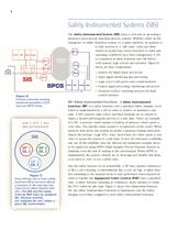
4 Safety Instrumente! Systems (SIS) The Safety Instrumente System (SIS) plays a vital role in providing a protective layer around industrial process Systems. Whether called an SIS, emergency or safety shutdown system, or a safety interlock, its purpose is to take process to a "safe state" when pre-deter- _fpj _ mined set points have been exceeded or when safe ^ 驗' operating conditions have been transgressed. A SIS is comprised of safety functions (see SIF below) with sensors, logic solvers and actuators. Figure B shows its basic components: ITT3J-1 * Sensors for signal input and power ו Input...
Open the catalog to page 4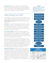
5 Safety Life Cycle. Earlier we mentioned how a Hazard and Risk Assessment study will determine the need for an SIS. This assessment is one part of a safety life cycle which all major safety standards have speci-fied. The safety life cycle shows a systematic approach for the development of a SIS. A simplified version is shown in Figure D. Figure D The Safety Life Cycle is a sequential approach to developing a Safety Instrumented System (SIS). References to a Safety Life Cycle can be found in ANSI/ISA 84.00.01 Parts 1-3; IEC 61508 Part 1; and IEC 61511 Parts 1-3. Safety Integrity Level (SIL) To...
Open the catalog to page 5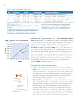
6 ure E SIL and Related Measures* SIL PFDavg 4 >99.99% 10-5 to <10-4 100,000 to 10,000 Potential for fatalities in the community 3 99.9% 10-4 to <10-3 10,000 to 1,000 Potential for multiple on-site fatalities 2 99 to 99.9% 10-3 to <10-2 1,000 to 100 Potential for major on-site injuries or a fatality 1 90 to 99% 10-2 to <10-1 100 to 10 Potential for minor on-site injuries SIL: Safety Integrity Level. AVAILABILITY: The probability that equipment will perform its task. PFDavg: The average PFD used in calculating safety system reliability. (PFD: Probability of Failure on Demand is the probability...
Open the catalog to page 6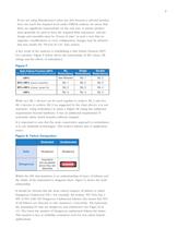
7 If you are using Manufactures prior use data because a selected product does not reach the required level under FMEDA analysis, be aware that there are significant requirements on the end user. A mature product must generally be used to have the required field experience, and the design and assembly must be "frozen in time" in such a way that no upgrades, modifications or even configuration changes may be allowed that may render the "Proven In Use" data useless. A key result of the analyses is establishing a Safe Failure Fraction (SFF) for a product. Figure F below shows the relationship of...
Open the catalog to page 7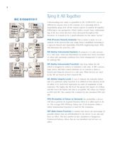
8 IEC61508/61511 Tying It All Together Understanding how safety is quantified in IEC 61508/61511 can be difficult for anyone new to the concept. It is a daunting task to immediately grasp how all the various aspects of analysis fit together. Following is one perspective which yields a sound, basic understand-ing of the key terms that have been discussed throughout this brochure. It is meant to be a quick-reference for the safety "novice." PHA (Process Hazards Analysis): This is where it starts. It is an analysis of the process that may range from a simplified screening to a rigorous Hazard and...
Open the catalog to page 8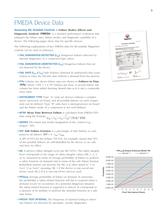
9 FMEDA Device Data Assessing SIL-Suitable Controls A Failure Modes, Effects and Diagnostic Analysis (FMEDA) is a detailed performance valuation that estimtes the failure rates, failure modes, and diagnostic capability of a device. The following pages show data for specific devices. The following explanations of key FMEDA data for SIL-suitable Magnetrol controls can be used as reference: 颕 FAIL DANGEROUS DETECTED (Xdd) Dangerous failures detected by internal diagnostics or a connected logic solver. FAIL DANGEROUS UNDETECTED (Xdu) Dangerous failures that are not detected by the device. Օ FAIL...
Open the catalog to page 9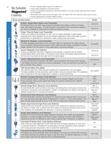
10 SIL-Suitable Magnetrol Controls The SIL indicated below is per IEC 61508/61511. Failure rates expressed in FITS and Annual. PFDavg is calculated according to a proof test interval of one year, though other proof test intervals can be applied. Transmitter failure rates assume the logic solver can detect both over-scale and under-scale currents. Contact Magnetrol for complete FMEDA reports. Sries and Description Model Eclipse® Guided Wave Radar Level Transmitter The Model 705 is a 24 VDC loop-powered transmitter that utilizes a variety of Coaxial, Twin, and Single rod probes. The performance...
Open the catalog to page 10All Magnetrol - AMETEK catalogs and technical brochures
 Eclipse® 706 Hygienic
12 Pages
 TUFFY® II
12 Pages
 E4 Modulevel®
12 Pages
 Thermatel® TD1/TD2
16 Pages
 Crude Oil Processing
8 Pages
 Natural Gas Processing
12 Pages
 Interface In The Field
14 Pages
 Emulsion In The Field
9 Pages
 PRODUCT LINE CATALOGUE
106 Pages
 Aurora® Magnetic Level Indicator
28 Pages
 Atlas™ Magnetic Level Indicator
24 Pages
 Echotel® 355
4 Pages
 STEAM DRUM LEVEL MATTERS
1 Page
 INTERFACE IN THE FIELD
1 Page
 Power Generation
16 Pages
 Petroleum Refining
16 Pages
 Seal Pots
4 Pages
 Mass Flow Measurement
12 Pages
 Heat Rate Awareness
8 Pages
 Ethylene Applications
8 Pages
 GEMINI™
32 Pages
 Pneumatic Tuffy®
12 Pages
 Models T5x & T6x
8 Pages
 Models T20/T21
12 Pages
 Series B73 and Series 75
12 Pages
 Series 3
24 Pages
 Model J52
2 Pages
 Model B40
4 Pages
 Floating Roof Detection
16 Pages
 Displacer Switches
20 Pages
 APM Pneumatic Modulevel®
12 Pages
 Flue Gas Desulferization
8 Pages
 Energy Management
4 Pages
 API 2350 Overfill Prevention
8 Pages
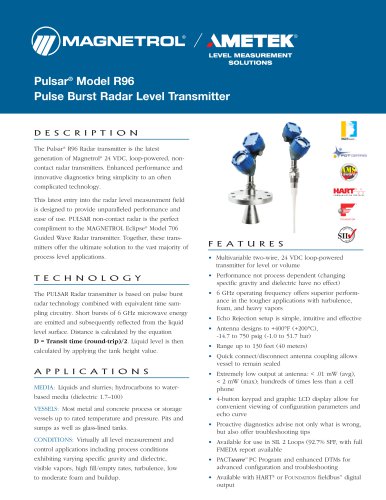
 PULSAR ® R96
1 Page
 Water & Wastewater
12 Pages
 Displacer Transmitters
4 Pages
 Guided Wave Radar
12 Pages
 Magnetic Level Indicators
12 Pages
 Thermal Dispersion
12 Pages
 Ultrasonic Contact
4 Pages
 R Series High Temp Switch
12 Pages
 Series K Pneumatic Switch
8 Pages
 J Series Pneumatic Switch
8 Pages
 Liquid Displacer Level Switches
16 Pages
 Crude Oil Processing
8 Pages
 Product Line Quick Reference
8 Pages





- MAGNETROL level switch
- MAGNETROL liquid level switch
- Level probe
- Liquid level sensor
- Measurement software
- Interface software
- MAGNETROL float level switch
- Analog level sensor
- MAGNETROL stainless steel level switch
- MAGNETROL liquid level transmitter
- Digital output level sensor
- MAGNETROL threaded level switch
- Vessel level sensor
- MAGNETROL analog level transmitter
- Liquids level gauge
- MAGNETROL tank level switch
- Flow sensor
- MAGNETROL magnetic float level switch
- Flow switch