- Catalogs
- Magnetrol - AMETEK
- PowerGen - A Guide to Level Instruments for Power Generating Plants
PowerGen - A Guide to Level Instruments for Power Generating Plants

PowerGen - A Guide to Level Instruments for Power Generating Plants
This document serves as a comprehensive guide to level instrumentation in power generating plants, focusing on systems such as pollution control, combustion fuel, steam generation, and water treatment. It discusses the evolution of power generation technology and highlights Magnetrol International's contributions to advancing level control solutions.
- Coal Storage: Raw coal is stored in silos and hoppers post-crushing. Explosion-proof level instrumentation is essential due to coal dust ignition risks.
- Natural Gas Separator: Separates solids and liquids from gas streams, requiring precise liquid level control to prevent compressor inlet contamination.
- Fuel Oil Storage: Used for boiler ignition, necessitating safety-certified switches and transmitters due to fire hazards.
- Ammonia Storage: Utilized in emissions control systems, requiring safety measures to prevent hazardous releases.
- Condenser Hotwell: Serves as a reservoir for turbine cycles, with level control ensuring adequate make-up water supply.
- Condensate Storage: Stores excess condensate from the hotwell, with proper level control vital for maintaining water supply.
- Deaerator: Removes gases from feedwater, with level controls managing fluctuating pressures and temperatures.
- Feedwater Heaters: Use turbine steam to heat water, with level control preventing overflow and ensuring efficient operation.
- Steam Drums: Interface between water and steam, requiring constant liquid levels for steam quality.
- Source Water and Demineralization: Ensures water quality for steam generation.
- Cooling Towers and Sumps: Manage heat dissipation and water recycling.
The guide emphasizes selecting appropriate level control instruments based on specific plant requirements and suggests consulting with Magnetrol representatives for tailored solutions.
Magnetrol International is a pioneer in level control technology, offering innovative solutions for power generation applications designed to enhance safety, efficiency, and reliability in power plants.
- Boiler Blowdown Tank: Receives continuous blowdown from the steam drum, with proper tank level controls preventing catastrophic explosions. Recommended instruments include the Eclipse Model 705 Guided Wave Radar Transmitter.
- Flash Tank: Collects condensate drain lines, with level measurement essential due to elevated temperatures and pressures. Instruments like the Eclipse Model 705 and Atlas Magnetic Level Indicators are recommended.
- Feedwater Evaporator: Purifies feedwater by evaporating raw water, with level instrumentation choice depending on chemical composition and storage requirements.
- Water Services: Storage tanks support plant operations, with effective level measurement and flow detection critical. Recommended instruments include the Eclipse Model 705 and Pulsar Model R95.
- Open Atmosphere Sumps: Collect and treat waste liquids in wastewater treatment areas, with level controls needing to withstand corrosive media and harsh conditions. Instruments like Echotel Models 300 and Eclipse Model 705 are suggested.
- Cooling Tower Basin: Rejects waste heat from the steam cycle, with level control necessary to prevent overflow and freezing in cold climates. Recommended instruments include the Eclipse Model 705 and Kotron Models 82CE.
- Lubrication Oil Tanks: Store lubricating oil for turbines and generators, with adequate level monitoring ensuring proper equipment functioning. Instruments like the Eclipse Model 705 and Pulsar Model R95 are recommended.
- Water Wash Tanks: Used for compressor washing, requiring level monitoring to manage wastewater discharge. Instruments like Echotel Models 300 and Eclipse Model 705 are suggested.
The document underscores the importance of selecting appropriate level measurement instruments based on specific application requirements and environmental conditions, with Magnetrol providing a range of suitable instruments for various industrial needs.
Catalog excerpts

I N D U S T R Y A P P L I C A T I O N S S E R I E S A Guide to Level Instrumentation for Power Generating Plants
Open the catalog to page 1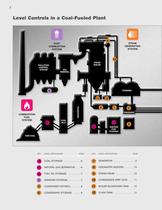
POLLUTION CONTROL SYSTEM RAW COAL TURBINES STEAM BOILER CONDENSER SO2 REMOVAL COAL STORAGE . . . . . . . . . . . . .6 NATURAL GAS SEPARATOR . . . .6 FUEL OIL STORAGE . . . . . . . . . .7 AMMONIA STORAGE . . . . . . . . . .7 CONDENSER HOTWELL . . . . . . .8 CONDENSATE STORAGE . . . . . .8 1 DEAERATOR . . . . . . . . . . . . . . . . .9 FEEDWATER HEATERS . . . . . . .10 STEAM DRUM . . . . . . . . . . . . . .10 CONDENSATE DRIP LEGS . . . . .11 BOILER BLOWDOWN TANK . . .12 FLASH TANK . . . . . . . . . . . . . . . .12 Level Controls in a Coal-Fueled Plant 1 PULVERIZER COAL SILO COMBUSTION FUEL SYSTEM...
Open the catalog to page 2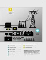
WATER TREATMENT GENERATOR POWER CONVERSION SYSTEM CIRCULATING WATER SYSTEM SOURCE WATER . . . . . . . . . . . .13 DEMINERALIZATION . . . . . . . . .14 MAKE-UP WATER . . . . . . . . . . . .14 SERVICE WATER . . . . . . . . . . . .15 OPEN SUMPS . . . . . . . . . . . . . .16 COOLING TOWER . . . . . . . . . . .16 LUBRICATION OIL TANK . . . . . .17 WATER WASH TANK . . . . . . . . .17 COOLING TOWER 13 14 15 16 17 18 Please Note: The level instruments recommended in this guide are based on field experience with similar applications and are included as a general guide to level control selection. Because...
Open the catalog to page 3
GAS TURBINE CONDENSER Level Controls in a Combined-Cycle Plant STEAM TURBINE HRSG HEAT RECOVERY STEAM GENERATOR FUEL 9 5 6 8 7 KEY LEVEL APPLICATION PAGE KEY LEVEL APPLICATION PAGE 3 POST COMBUSTION SYSTEM COMBUSTION FUEL SYSTEM STEAM GENERATING SYSTEM NATURAL GAS SEPARATOR . . . .6 FUEL OIL STORAGE . . . . . . . . . .7 AMMONIA STORAGE . . . . . . . . . .7 CONDENSER HOTWELL . . . . . . .8 CONDENSATE STORAGE . . . . . .8 DEAERATOR . . . . . . . . . . . . . . . . .9 FEEDWATER HEATERS . . . . . . .10 HRSG DRUM . . . . . . . . . . . . . . .10 CONDENSATE DRIP LEGS . . . . .11 FLASH TANK . . . . ....
Open the catalog to page 4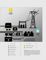
WATER TREATMENT GENERATOR POWER CONVERSION SYSTEM CIRCULATING WATER SYSTEM SOURCE WATER . . . . . . . . . . . .13 DEMINERALIZATION . . . . . . . . .14 MAKE-UP WATER . . . . . . . . . . . .14 SERVICE WATER . . . . . . . . . . . .15 OPEN SUMPS . . . . . . . . . . . . . .16 COOLING TOWER . . . . . . . . . . .16 LUBRICATION OIL TANK . . . . . .17 WATER WASH TANK . . . . . . . . .17 COOLING TOWER 13 14 15 16 17 18 Please Note: The level instruments recommended in this guide are based on field experience with similar applications and are included as a general guide to level control selection. Because...
Open the catalog to page 5
One hundred years ago, electric power was over 20 cents a kilowatt-hour— more than twenty times today’s cost. Back then electricity was used primarily in cities for lighting streets and powering streetcars. The cost of electric power was well beyond the means of most families. Even rudimentary appliances were absent from American homes. But the 20th century brought Power to the People through improved power-generating technology. By century’s end, affordable electricity was available to all Americans. As the power industry matured, a Chicago company that first marketed its level controls for...
Open the catalog to page 6
Application: Raw coal is delivered to a coal yard in aggregate pieces of approximately 6" that are later reduced in size by a crusher to approximately 1.5". Enclosed storage of crushed coal is common in frigid climates and where containment of coal dust is controlled to protect populated areas. Hoppers and silos store active and reserve crushed coal prior to its pulverization into the powdered form suitable for boiler combustion. Challenges: Some severe power plant accidents in years past have been traced to coal dust ignition, and the atmospheres of contained coal storage areas are highly congested...
Open the catalog to page 7
Application: Fuel-fed ignitors initiate the boiler flame in coal-fed plants using natural gas or atomized fuel oils such as light grade #2 or heavy grade #6. Natural gas and propane can also be used. In combined-cycle plants, gas turbines often use natural gas and liquid fuel oils as ignition fuel. Large gas turbines are designed to operate alternately or simultaneously with both gas and liquid fuels. In dual-fuel plants, a False Start Tank will temporarily hold diesel fuel after an unsuccessful attempt to fire the turbine. Challenges: Crude oils with lower flash points represent a greater fire...
Open the catalog to page 8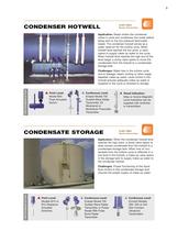
Application: Steam enters the condenser where it cools and condenses into water before being sent to the low-pressure feed-water heater. The condenser hotwell serves as a water reservoir for the turbine cycle. When hotwell level reaches the low point, a valve opens to supply make-up water to the cycle. When hotwell level reaches the high end of the level range, a dump valve opens to move the condensate from the hotwell to a condensate storage tank. Challenges: Water loss in the turbine cycle due to leakage, steam venting or other usage depletes make-up water. Level control in the hotwell ensures...
Open the catalog to page 9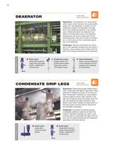
Application: The deaerator is an open-faced water heater which removes non-condensable gases from the feedwater. In addition to the condenser hotwell, the deaerator's storage tank is the remaining reservoir in the turbine cycle. Positioned below the deaerator and before the boiler feed pumps, the deaerator storage tank serves as a surge tank for the boiler feedwater. Tank level is often controlled by a control valve on the condensate supply line to the deaerator. Challenges: Pressure fluctuations are extensive in the deaerator storage tank and result in flashing. Level controls must contend with...
Open the catalog to page 10
Application: Feedwater heaters use extraction steam from the turbine to raise the temperature of water destined for the boiler. Water first passes through low-pressure heaters and into the deaerator where excess oxygen is removed. The feedwater then passes into the high-pressure heaters where it is further heated and pressurized. Two separate level control loops should manage each feedwater heater—according to ASME standards. Challenges: Feedwater heater level is controlled to (1) prevent level from rising into the extraction line; (2) keep the tube surfaces in the condensing zone immersed; and...
Open the catalog to page 11All Magnetrol - AMETEK catalogs and technical brochures
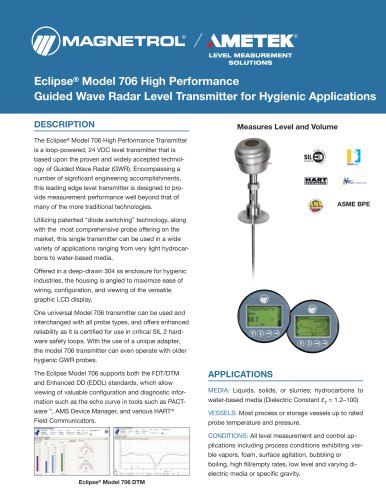 Eclipse® 706 Hygienic
12 Pages
 TUFFY® II
12 Pages
 E4 Modulevel®
12 Pages
 Thermatel® TD1/TD2
16 Pages
 Crude Oil Processing
8 Pages
 Natural Gas Processing
12 Pages
 Interface In The Field
14 Pages
 Emulsion In The Field
9 Pages
 PRODUCT LINE CATALOGUE
106 Pages
 Aurora® Magnetic Level Indicator
28 Pages
 Atlas™ Magnetic Level Indicator
24 Pages
 Echotel® 355
4 Pages
 STEAM DRUM LEVEL MATTERS
1 Page
 INTERFACE IN THE FIELD
1 Page
 Power Generation
16 Pages
 Petroleum Refining
16 Pages
 Seal Pots
4 Pages
 Mass Flow Measurement
12 Pages
 Heat Rate Awareness
8 Pages
 Ethylene Applications
8 Pages
 GEMINI™
32 Pages
 Pneumatic Tuffy®
12 Pages
 Models T5x & T6x
8 Pages
 Models T20/T21
12 Pages
 Series B73 and Series 75
12 Pages
 Series 3
24 Pages
 Model J52
2 Pages
 Model B40
4 Pages
 Floating Roof Detection
16 Pages
 Displacer Switches
20 Pages
 APM Pneumatic Modulevel®
12 Pages
 Flue Gas Desulferization
8 Pages
 Energy Management
4 Pages
 API 2350 Overfill Prevention
8 Pages
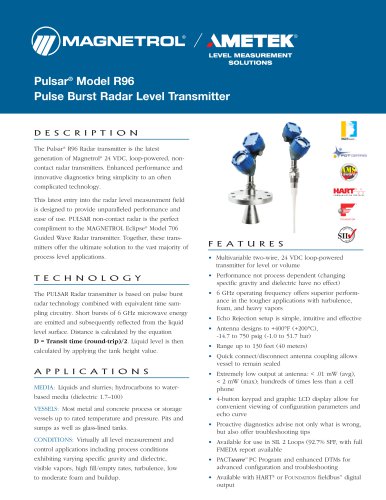
 PULSAR ® R96
1 Page
 Water & Wastewater
12 Pages
 Displacer Transmitters
4 Pages
 Guided Wave Radar
12 Pages
 Magnetic Level Indicators
12 Pages
 Thermal Dispersion
12 Pages
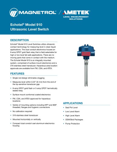
 Ultrasonic Contact
4 Pages
 R Series High Temp Switch
12 Pages
 Series K Pneumatic Switch
8 Pages
 J Series Pneumatic Switch
8 Pages
 Liquid Displacer Level Switches
16 Pages
 Crude Oil Processing
8 Pages
 Product Line Quick Reference
8 Pages


- MAGNETROL level switch
- MAGNETROL liquid level switch
- Level probe
- Liquid level sensor
- Interface software
- Measurement software
- MAGNETROL float level switch
- Analog level sensor
- MAGNETROL stainless steel level switch
- MAGNETROL level transmitter
- MAGNETROL liquid level transmitter
- Digital output level sensor
- MAGNETROL threaded level switch
- Vessel level sensor
- MAGNETROL analog level transmitter
- Liquids level gauge
- MAGNETROL tank level switch
- Flow sensor
- MAGNETROL magnetic float level switch
- Flow switch