
- Catalogs
- Magnetrol - AMETEK
- Model T10 Cable Mounted Float Level

Model T10 Cable Mounted Float Level
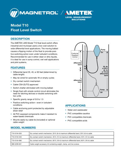
Model T10 Cable Mounted Float Level
- Differential band options of 20, 40, or 60 feet, determined by cable length.
- Can be wired for automatic fill or empty cycles.
- Dry contact switch mechanism with CSA-approved cable.
- Eliminates switch chatter with moving ballast.
- Single float design with a simple control circuit.
- Specific gravity range from 0.6 to 1.5.
- Resistant to water-based chemicals due to PVC components.
- Easy mounting with included cable tie or optional cable weight.
- Switch type: SPDT dry contact.
- Process temperature: Maximum +140 °F (+60 °C).
- Ambient temperature: +32 to +140 °F (0 to +60 °C).
- Specific gravity: 0.6 minimum / 1.5 maximum.
- Maximum float switch current and voltage specifications provided.
- Materials: PVC with neoprene strain relief and Buna cosmetic ring.
Catalog excerpts
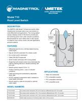
LEVEL MEASUREMENT SOLUTIONS The AMETEK LMS Model T10 float level switch offers industrial and municipal users a low-cost solution to wide differential level applications. The moving ballast causes a flipping motion of the float to provide positive switching action even under turbulent conditions. Recommended for use in either clean or dirty liquids, it is ideal for use in sump control, wet well applications and pilot systems. • Differential band 20, 40, or 60 feet (determined by cable length) • May be wired for automatic fill or empty cycles • Dry contact switch mechanism • Cable CSA (SJTO) approved • Switch chatter eliminated with moving ballast • Single float with simple control circuit eliminates the need for latching devices or double switching with two units • Specific gravity range of 0.6 to 1.5 • Positive switching action-even in turbulent conditions • Cable anchoring point protected by adjustable strain relief • All PVC exposed components make it resistant to water-based chemicals • Mounts easily by cable tie (included) or optional cable weight MODEL NUMBERS
Open the catalog to page 1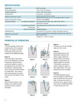
Figure 1 T10 level switches contain a dry contact switch with a swinging ballast. The cable on the float is anchored in the tank at the midpoint of the differential band. As the level falls to the lowest point of the differential, the cable is pulled taut, tilting the float, causing the ballast to swing to the opposite end of the float. The float reacts in a flipping action which causes the switch contacts to change state. The minimum level recommended is 6 inches (152 mm) from the bottom of the vessel. Contacts have not yet changed state with rise in level. As the highest point of the differential...
Open the catalog to page 2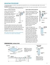
MOUNTING PROCEDURE T10 level switch may be mounted by using cable ties included with the unit, or by the optional cable weight which must be purchased separately. CAUTION: The recommended method of carrying the T10 is by the cable. The unique moving ballast in the unit may cause it to unexpectedly flip out of the individual’s hands. Cable weight method (optional) Cable tie method (standard) A pipe or other structure must be available in the tank to which the plastic cable tie may be affixed. Refer to Figure 7. Position the adjustable strain relief on the cable to allow one-half of the distance...
Open the catalog to page 3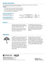
WIRING PROCEDURE The T10 float level switch may be wired for fill or empty pump control functions or as a high or low level alarm. Wire according to the terminal connection drawing below. CAUTION: 1. The unused wire (third wire) must be electrically insulated. 2. Do not fasten electrical cable onto rough or sharp surfaces. 3. Use only on equipment with thermal overload protection. 4. Consult local codes for proper application. FOR EMPTY PUMP CONTROL OR HIGH ALARM FUNCTIONS Connect the blue and black wires. FOR FILL PUMP CONTROL OR LOW ALARM FUNCTIONS Line Out to Load Line In Line Out to Load...
Open the catalog to page 4All Magnetrol - AMETEK catalogs and technical brochures
 Echotel® Model 355
8 Pages
 L312E SERIES
2 Pages
 L312 SERIES
2 Pages
 L250AD SERIES
1 Page
 L195 SERIES
1 Page
 S003 series
1 Page
 JUPITER® Model JM4
20 Pages
 Model OES Point Level Switch
2 Pages
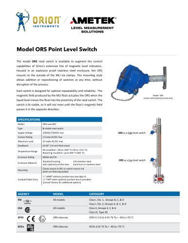 Model ORS Point Level Switch
2 Pages
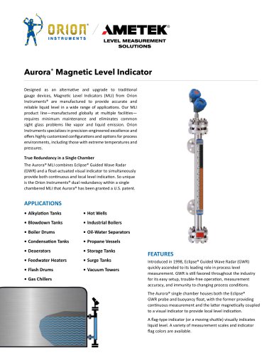 Aurora® Magnetic Level Indicator
28 Pages
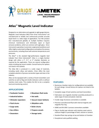 142_orion_atlas_mli
28 Pages
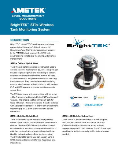 BrightTEK™ ST9x Wireless
12 Pages

Archived catalogs
 Product Line Quick Reference
8 Pages
 Crude Oil Processing
8 Pages
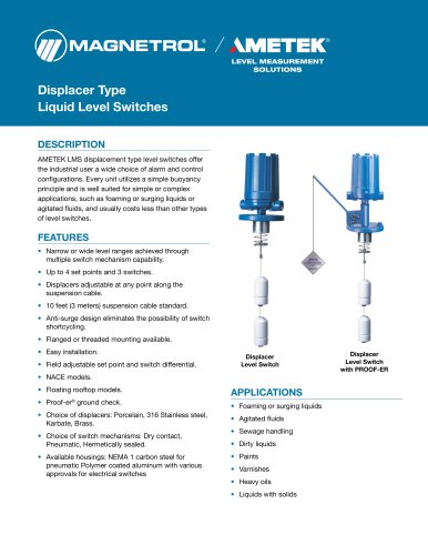
 Liquid Displacer Level Switches
16 Pages
 J Series Pneumatic Switch
8 Pages
 Series K Pneumatic Switch
8 Pages
 R Series High Temp Switch
12 Pages
 Ultrasonic Contact
4 Pages
 Thermal Dispersion
12 Pages
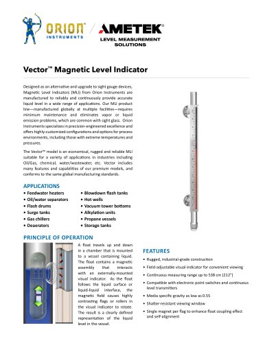
 Magnetic Level Indicators
12 Pages
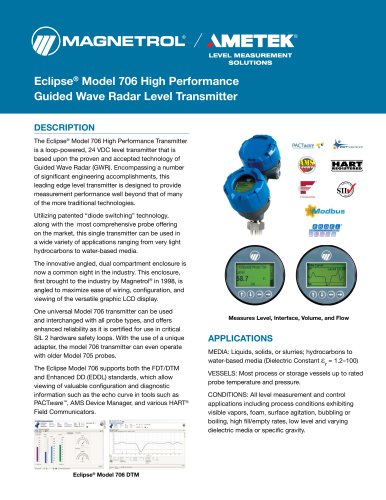
 Guided Wave Radar
12 Pages
 Displacer Transmitters
4 Pages
 Water & Wastewater
12 Pages
 PULSAR ® R96
1 Page
 API 2350 Overfill Prevention
8 Pages
 Energy Management
4 Pages
 Flue Gas Desulferization
8 Pages
 APM Pneumatic Modulevel®
12 Pages
 Displacer Switches
20 Pages
 Floating Roof Detection
16 Pages
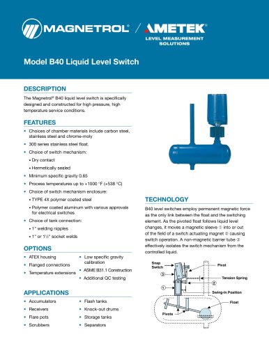 Model B40
12 Pages
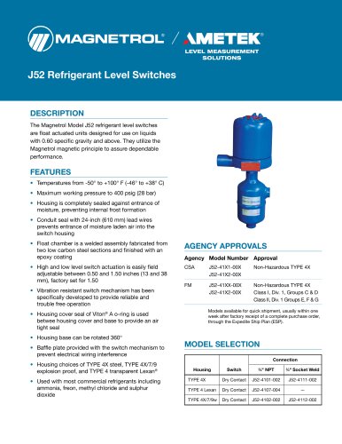 Model J52
2 Pages
 Series 3
24 Pages
 Series B73 and Series 75
12 Pages
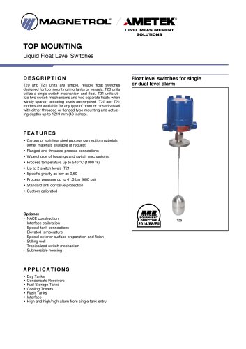 Models T20/T21
12 Pages
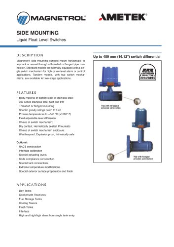 Models T5x & T6x
12 Pages
 Pneumatic Tuffy®
12 Pages
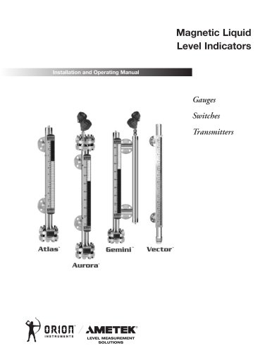 GEMINI™
20 Pages
 Ethylene Applications
8 Pages
 Heat Rate Awareness
8 Pages
 Mass Flow Measurement
12 Pages
 Seal Pots
4 Pages
 Petroleum Refining
16 Pages
 Power Generation
16 Pages
 INTERFACE IN THE FIELD
1 Page
 STEAM DRUM LEVEL MATTERS
1 Page
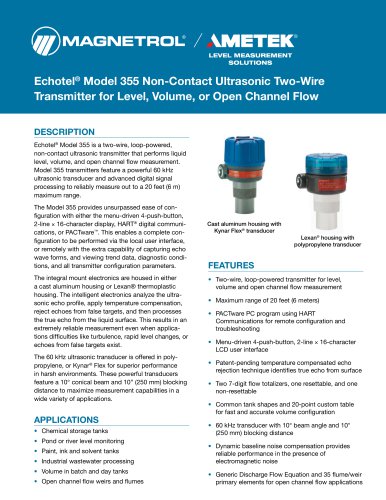 Echotel® 355
8 Pages
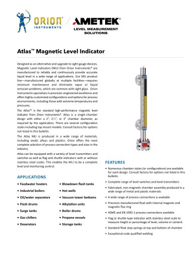 Atlas™ Magnetic Level Indicator
28 Pages
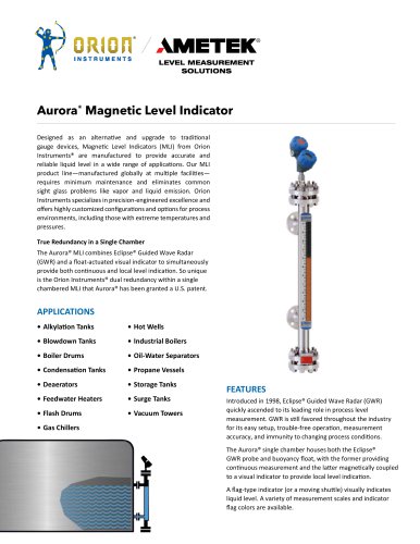 Aurora® Magnetic Level Indicator
28 Pages
 PRODUCT LINE CATALOGUE
106 Pages
 Emulsion In The Field
9 Pages
 Interface In The Field
14 Pages
 Natural Gas Processing
12 Pages
 Crude Oil Processing
8 Pages
 Thermatel® TD1/TD2
16 Pages
 E4 Modulevel®
12 Pages
 TUFFY® II
12 Pages
 Eclipse® 706 Hygienic
12 Pages


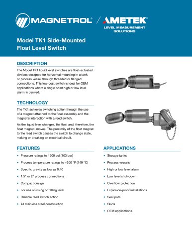







- MAGNETROL liquid level switch
- Level probe
- Liquid level sensor
- Measurement software
- Interface software
- Analog level sensor
- MAGNETROL stainless steel level switch
- MAGNETROL level transmitter
- MAGNETROL liquid level transmitter
- Digital output level sensor
- MAGNETROL threaded level switch
- Vessel level sensor
- MAGNETROL analog level transmitter
- Liquids level gauge
- MAGNETROL tank level switch
- Flow sensor
- MAGNETROL magnetic float level switch
- Flow switch