
- Catalogs
- Magnetrol - AMETEK
- JUPITER® Model JM4

JUPITER® Model JM4

JUPITER® Model JM4
The Jupiter® Model JM4 is a high-performance magnetostrictive level transmitter used for precise liquid level measurement. It operates by sending an electrical pulse through a magnetostrictive wire, interacting with magnets in a float to determine liquid levels. The mechanical wave generated is converted back into electrical energy, allowing the system to interpret the float's position.
Installation and Configuration:
The transmitter can be installed directly into a vessel or mounted externally on a magnetic level indicator (MLI). It features a user-friendly interface with a local push-button system, a 310° rotatable head for better display visibility, and advanced remote interaction capabilities through EDDL and DTM.
Advanced Features:
The Jupiter offers high accuracy measurement with ±0.05 inches (1.3 mm) precision. It includes a removable and rotatable transmitter head for flexible installation and maintenance. The system supports auto-configuration with a Smart Probe, transferring configuration settings automatically.
Performance and Reliability:
Designed to handle challenging conditions such as foaming media and buildup, the transmitter uses buoyancy-based technology for reliable performance in various applications, including those with emulsion layers and specific gravity fluctuations.
Technical Specifications:
- Measurement Principle: Magnetostriction
- Input: Level, response signal time of flight
- Output: 4 to 20 mA with HART, Foundation fieldbus™
- Accuracy: ±0.01% full scale or ±0.05 in (1.3 mm)
- Operating Temperature: -40 to +158 °F (-40 to +70 °C)
- Process Pressure: Vacuum to 3000 psig (207 bar)
- Housing Material: IP67/die cast aluminum or stainless steel
Environmental and Safety Standards:
The device meets CE requirements for electromagnetic compatibility and is certified for functional safety to SIL 2/3 according to IEC 61508. It is designed to withstand harsh environmental conditions, including high temperatures and pressures.
Conclusion:
The Jupiter® Model JM4 magnetostrictive level transmitter is a versatile and reliable solution for precise level measurement in various industrial applications. Its advanced features and robust design make it suitable for challenging environments, ensuring accurate and consistent performance.
Specifications:
The document outlines the specifications for the Jupiter JM4 model, a direct insertion probe used for level/interface measurement. It supports standard, high-temperature, and cryogenic process temperatures ranging from -320°F to +800°F. The maximum probe length is 400 inches, with limitations based on configuration. The probe is available in various materials, including 316 SS, Hastelloy C276, and Monel 400, with options for Teflon or PFA coatings.
Procedures:
Installation considerations include ensuring adequate overhead clearance and selecting appropriate chamber or stilling well sizes. The document provides detailed instructions for specifying probe length and selecting the correct float for total and interface level measurements.
Standards and Approvals:
The Jupiter JM4 complies with multiple standards, including ATEX, IECEx, and FM approvals for explosion-proof, flameproof, non-incendive, intrinsically safe, and dust ignition-proof environments. It adheres to directives such as EMC 2004/108/EC, PED 97/23/EC, and ATEX 2014/34/EU.
Recommendations:
Special conditions of use include precautions against ignition by impact or friction, maintaining enclosure temperatures, minimizing electrostatic discharge, and ensuring transient overvoltage protection. The document advises consulting the manufacturer for flameproof joint repairs and using certified plugs for unused openings.
Key Data from Tables:
The document includes tables detailing probe configurations, material properties, float dimensions, and temperature-pressure ratings. It specifies minimum liquid specific gravities for different float materials and provides a sizing chart for chambers and stilling wells.
Critical Information:
Users must follow installation instructions, use agency-approved barriers, and ensure proper grounding for explosion-proof and intrinsically safe installations. The document emphasizes the importance of using suitable wire for supply connections and maintaining temperature codes for Ex db ratings.
Catalog excerpts

MAGNETOSTRICTIVE LEVEL TRANSMITTER
Open the catalog to page 1
MAGNETOSTRICTION WORKS LOW-VOLTAGE PULSE On-board electronics send a low-voltage electrical pulse down the magnetostrictive wire at the speed of light, ten times per second. MAGNETS Magnets contained within the float focus their energy toward the wire at the precise location of the liquid level. DIRECT INSERTION TWIST Interaction between the magnetic field, electrical pulse, and magnetostrictive wire cause a slight mechanical disturbance in the wire that travels back up the probe at the speed of sound. PIEZOELECTRIC CRYSTALS The mechanical wave is converted back into electrical energy by two...
Open the catalog to page 2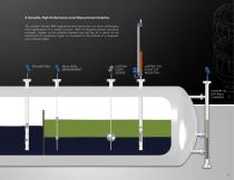
A Versatile, High-Performance Level Measurement Solution The Jupiter® Model JM4 magnetostrictive transmitter can solve challenging level applications in a variety of ways. With its magnetic-based operating principle, Jupiter can be directly inserted into the top of a vessel via an assortment of connection types, or mounted on the outside of a magnetic level indicator (MLI). STILLING WELL DUAL-LEVEL MEASUREMENT CUSTOM FLOAT DESIGN JUPITER® ON ATLAS TOP MOUNT MLI JUPITER® IN EXTERNAL CHAMBER
Open the catalog to page 3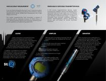
HIGH ACCURACY MEASUREMENT REMOVABLE & ROTATABLE TRANSMITTER HEAD In an era of technologically advanced “smart” instruments, plants and operators are investing and placing more reliance in device networks which deliver reliable level measurement with a high degree of accuracy. The Jupiter magnetostrictive level transmitter is capable of measuring with an impressive accuracy of ±0.05 inches (1.3 mm), allowing facilities tighter level tolerances, optimizing their process operations and generating greater ROI. Jupiter possesses a comprehensive array of advanced diagnostics and real-time performance...
Open the catalog to page 4
REMOTE MOUNT OPTION IDEAL FOR INSTALLATION SPACE CONSTRAINTS 45° ANGLED ENCLOSURE CONVENIENT VISIBILITY & ACCESSIBILITY
Open the catalog to page 5
BUOYANCY A VERSATILE SOLUTION FOR A VARIETY OF APPLICATION CHALLENGES Buoyancy-based technologies have been utilized in the process instrumentation world for generations and are widely considered to provide reliable, accurate level measurement in an extensive range of applications and service conditions. Jupiter capitalizes on the benefits of buoyancy such as ease of installation, minimized configuration, ability to check calibration either by moving the float or utilizing an external magnetic field, customization of float size/shape/ materials, and high pressures. With the amazing accuracy of...
Open the catalog to page 6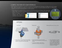
A SIMPLE, FEATURE-RICH USER INTERFACE Jupiter® takes the user experience to new levels of convenience and functionality with an information-rich display and an easy-to-navigate menu. With the new graphic LCD, waveforms are viewable locally at the device. You can also interface with Jupiter via a capable DCS or handheld communicator that utilize DDs/EDDL for remote connectivity. A fully redesigned and upgraded DTM puts real-time and historical trend data at your fingertips. With a basic laptop, a HART modem, and the free-to-download program PACTware™, the transmitter can be accessed locally or...
Open the catalog to page 7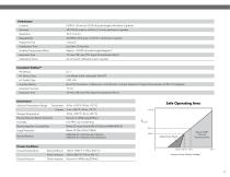
Foundation fieldbus™ Environment Ambient Temperature Range Transmitter: -40 to +158 °F (-40 to +70 °C) Process Pressure (Direct Insertion) Vacuum to 3000 psig (207bar) Electromagnetic Compatibility Meets CE requirement (EN 61326) and NAMUR NE 21 Surge Protection ANSI/ISA-S71.03 Class SA1 (Shock); ANSI/ISA-S71.03Class VC2 (Vibration) Safe Operating Area 1136 Q Process Conditions Process Temperature External Mount: -320 to +850 °F (-196 to 450 °C) Direct Insertion: -320 to 800 °F (-196 to 425 °C) Process Pressure Direct Insertion: Vacuum to 3000 psig (207bar)
Open the catalog to page 9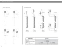
EXTERNAL MOUNT dashed line represents cryogenic insulation
Open the catalog to page 10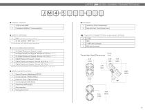
JUPITER JM4 MODEL NUMBER TRANSMITTER HEAD 2 Remote mount transmitter is not available with Digit 8 = 3, B, or D
Open the catalog to page 11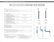
1 MLI insulation required for maximum temperature Left side mount (standard) Right side mount 3 Available only with Digit 3, Options F, H, L, M Standard Probe
Open the catalog to page 12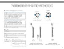
8 CHAMBER SIZE (FOR MOUNTING HARDWARE) Probe mounting positions on Atlas™, Vector™, and Gemini™ Magnetic Level Indicators Select these options if chamber DOES NOT contain high-temp insulation 9 UNUSED None 10 LEVEL/INTERFACE MEASUREMENT PREFERENCE 1 11,12 UNUSED 13-15 PROBE LENGTH SEE note 4 None Specify required insertion length. See right. Maximum Probe Length = 400 inches (999 cm) (limited to 180 inches (457 cm) when digit 3 = K, L or M) Top/Bottom Mount Offset Configuration Probe Length = Center-to-Center + 6 in. (15 cm) Top Mount Configuration Probe Length = Center-to-Center + 8 in. (20...
Open the catalog to page 13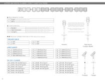
4&5 PROCESS CONNECTION SIZE & TYPE (Select from below) ASME FLANGES High-Temp & Cryogenic Models
Open the catalog to page 14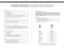
6 MATERIAL OF CONSTRUCTION wetted materials only 4 Maximum Probe Length = 400 inches (999 cm) (limited to 180 inches (457 cm) when digit 3 = 2) 3 Refer to sizing chart for chambers and stilling wells on page 16 10 LEVEL/INTERFACE MEASUREMENT PREFERENCE Units mounted in stilling wells or chambers are provided with centering discs at the base of the probe
Open the catalog to page 15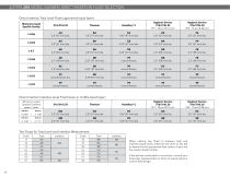
Direct Insertion Total Level Float (uppermost liquid layer) When utilizing two floats to measure total and interface liquid levels, reference the chart on the left to determine the appropriate float code to insert into the Jupiter model number. If the desired combination is not shown, consult your local sales representative or Orion to inquire about a custom float deisgn.
Open the catalog to page 16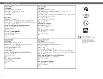
AGENCY APPROVALS Explosion Proof Flame Proof: Class I, Zone 0/1, AEx db IIB + H2 T1.. .T6 Ga/Gb (US) Class I, Zone 0/1, Ex db IIB + H2 T1...T6 Ga/GB (Canada) These units are in compliance with the EMC directive 2004/108/EC, the PED directive 97/23/ EC and the ATEX directive 2014/34/EU.
Open the catalog to page 18
JM4 Material Properties of Probe Partition Well 1. For Explosion-proof installations the I.S. ground terminal shall be connected to appropriate intrinsically safe ground in accordance with the Canadian Electrical code (CEC) or the national electrical code (NEC). For intrinsically safe installations the I.S. ground terminal does not require grounding. 2. Manufacturer's installation instructions supplied with the protective barrier and the CEC or the NEC must be followed when installing this equipment. Barrier must be certified for Canadian & U.S. installation. 3. Control equipment connected to...
Open the catalog to page 19All Magnetrol - AMETEK catalogs and technical brochures
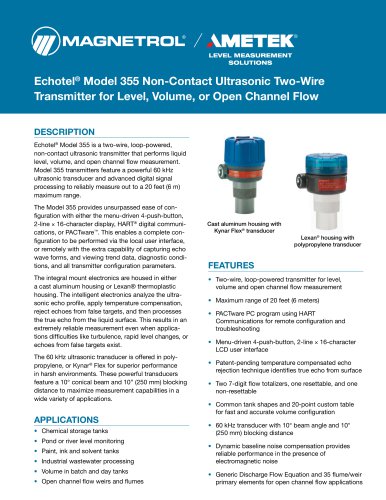 Echotel® Model 355
8 Pages
 L312E SERIES
2 Pages
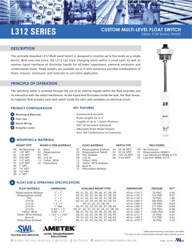 L312 SERIES
2 Pages
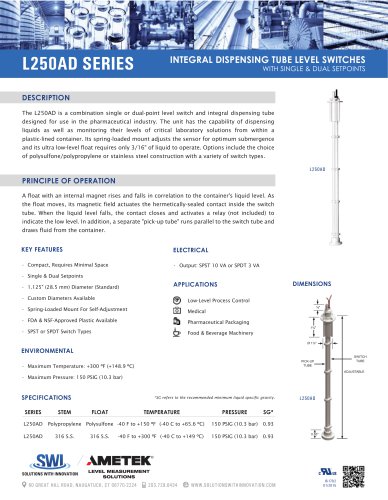 L250AD SERIES
1 Page
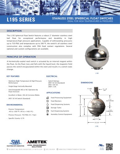 L195 SERIES
1 Page
 S003 series
1 Page
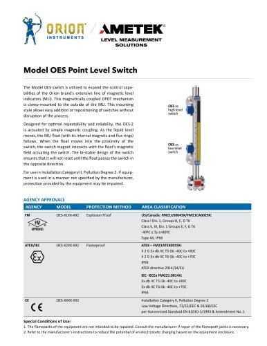 Model OES Point Level Switch
2 Pages
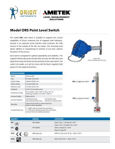 Model ORS Point Level Switch
2 Pages
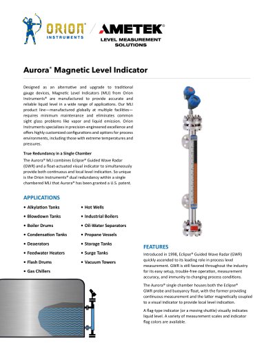 Aurora® Magnetic Level Indicator
28 Pages
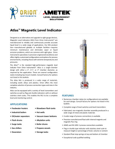 142_orion_atlas_mli
28 Pages
 BrightTEK™ ST9x Wireless
12 Pages
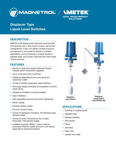



Archived catalogs
 Product Line Quick Reference
8 Pages
 Crude Oil Processing
8 Pages
 Liquid Displacer Level Switches
16 Pages
 J Series Pneumatic Switch
8 Pages
 Series K Pneumatic Switch
8 Pages
 R Series High Temp Switch
12 Pages
 Ultrasonic Contact
4 Pages
 Thermal Dispersion
12 Pages
 Magnetic Level Indicators
12 Pages
 Guided Wave Radar
12 Pages
 Displacer Transmitters
4 Pages
 Water & Wastewater
12 Pages
 PULSAR ® R96
1 Page
 API 2350 Overfill Prevention
8 Pages
 Energy Management
4 Pages
 Flue Gas Desulferization
8 Pages
 APM Pneumatic Modulevel®
12 Pages
 Displacer Switches
20 Pages
 Floating Roof Detection
16 Pages
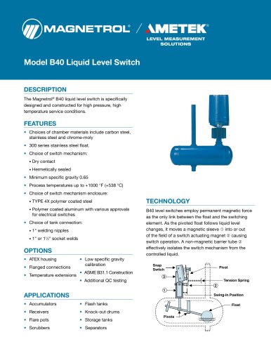 Model B40
12 Pages
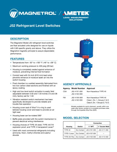 Model J52
2 Pages
 Series 3
24 Pages
 Series B73 and Series 75
12 Pages
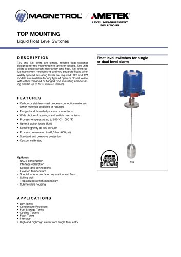 Models T20/T21
12 Pages
 Models T5x & T6x
12 Pages
 Pneumatic Tuffy®
12 Pages
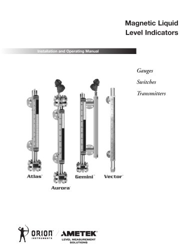 GEMINI™
20 Pages
 Ethylene Applications
8 Pages
 Heat Rate Awareness
8 Pages
 Mass Flow Measurement
12 Pages
 Seal Pots
4 Pages
 Petroleum Refining
16 Pages
 Power Generation
16 Pages
 INTERFACE IN THE FIELD
1 Page
 STEAM DRUM LEVEL MATTERS
1 Page
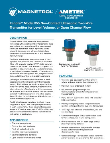 Echotel® 355
8 Pages
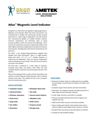 Atlas™ Magnetic Level Indicator
28 Pages
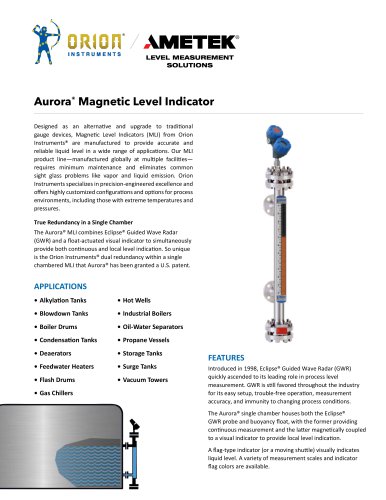 Aurora® Magnetic Level Indicator
28 Pages
 PRODUCT LINE CATALOGUE
106 Pages
 Emulsion In The Field
9 Pages
 Interface In The Field
14 Pages
 Natural Gas Processing
12 Pages
 Crude Oil Processing
8 Pages
 Thermatel® TD1/TD2
16 Pages
 E4 Modulevel®
12 Pages
 TUFFY® II
12 Pages
 Eclipse® 706 Hygienic
12 Pages














- MAGNETROL level switch
- MAGNETROL liquid level switch
- Level probe
- Liquid level sensor
- Measurement software
- Interface software
- MAGNETROL float level switch
- Analog level sensor
- MAGNETROL stainless steel level switch
- MAGNETROL liquid level transmitter
- Digital output level sensor
- MAGNETROL threaded level switch
- Vessel level sensor
- MAGNETROL analog level transmitter
- Liquids level gauge
- MAGNETROL tank level switch
- Flow sensor
- MAGNETROL magnetic float level switch
- Flow switch