
- Catalogs
- Magnetrol - AMETEK
- J Series Pneumatic Switch

J Series Pneumatic Switch

J Series Pneumatic Switch
Catalog excerpts

Series J Pneumatic Switch Mechanism Installation and Operating Manual Bleed Type Valve for Liquid Level Switches
Open the catalog to page 1
Read this Manual Before Installing This manual provides information on the Series J Pneumatic Switch Mechanism. It is important that all instructions are read carefully and followed in sequence. Detailed installation and hook-up instructions are included in this manual. Conventions Used in this Manual Certain conventions are used in this manual to convey specific types of information. General technical material, support data, and safety information are presented in narrative form. The following styles are used for notes, cautions, and warnings. Notes Notes contain information that augments or...
Open the catalog to page 2
Description The Series ‘J’ Pneumatic Switch is a single airline, bleed type valve with a magnetically actuated flapper. The movement of the magnet assembly causes the switch to change state, either moving the flapper away from the nozzle allowing the pressure in the line to vent or moving the flapper against the nozzle causing pressure to build up in the line. Principle of Operation Figure 1 shows the attraction sleeve and magnet in the position when the liquid level is such that the attraction sleeve is below the field of the magnet. In this position, the flapper has been drawn away from the...
Open the catalog to page 3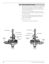
Reversing Pilot Action All Series J Pneumatic Switch Mechanisms are shipped from the factory set-up for direct action; closed at high level. They can be field modified for the reverse (open) position by following the steps below: 1. First remove the upper shoulder screw from the actuator link and move it from the direct (D) position to the reverse (R); refer to Figure 3. 2. Loosen the screw that positions the spring bracket and move it from the direct (D) position to the reverse (R) position; refer to Figure 4. 3. Fasten screw securely. The switch is now setup for reverse action. Enclosing tube...
Open the catalog to page 4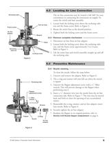
Locating Air Line Connection The air line connection may be rotated a full 360° for your convenience in connecting the instrument air supply. To rotate the switch and base assembly: 1. Loosen both the locking screw above the enclosing tube nut and the frame screw. Refer to Figure 5. 2. Rotate the entire base to the desired position. 3. Tighten both the locking screw and the frame screw. Enclosing tube Fall-out stop Frame screw Air line adapter Magnet 4.0.1 Remove complete mechanism 1. Disconnect air line from air line adapter. 2. Loosen both the locking screw above the enclosing tube nut, and...
Open the catalog to page 5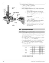
5.0.2 Nozzle flapper readjustment 1. Connect an air line to the adapter. 2. Pressurize the air line. 3. Adjust the flapper adjustment screw for the desired action: Enclosing tube Magnet (yellow or red dot) Floppy adjustment screw 1 ⁄16" Diameter wire Direct Action a. Hold the magnet against the enclosing tube. b. Adjust the flapper adjustment screw with a 1⁄16" Allen wrench until the air flow stops, plus an extra one-eighth turn. Reverse Action a. Hold the magnet against the fall out stop. Refer to Figure 5 on page 5. b. Adjust the flapper adjustment screw with a 1⁄16" Allen wrench until the...
Open the catalog to page 6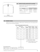
Switch housing replacement assembly Standard carbon steel housing replacement assemblies are available. Refer to Figure 8. Replacement Kit Part Number Description Standard housing cover Gray Cover Blue Cover Cover assembly hardware Includes assembly hardware kit 89-6508-001. Figure 8 Carbon steel housing assembly Switch Codes Magnetrol level controls are identified by an alpha-numeric numbering system. The last digits describe the type of switch mechanism furnished. SWITCH MECHANISM AND ENCLOSURE Switch Code Red Dot Maximum Orifice Maximum Process Diameter Supply Temp. in. (mm) For models rated...
Open the catalog to page 7
ASSURED QUALITY & SERVICE COST LESS Service Policy Return Material Procedure Owners of Magnetrol may request the return of a control or any part of a control for complete rebuilding or replacement. They will be rebuilt or replaced promptly. Controls returned under our service policy must be returned by Prepaid transportation. Magnetrol will repair or replace the control at no cost to the purchaser (or owner) other than transportation if: So that we may efficiently process any materials that are returned, it is essential that a “Return Material Authorization” (RMA) number be obtained from the...
Open the catalog to page 8All Magnetrol - AMETEK catalogs and technical brochures
 Eclipse® 706 Hygienic
12 Pages
 TUFFY® II
12 Pages
 E4 Modulevel®
12 Pages
 Thermatel® TD1/TD2
16 Pages
 Crude Oil Processing
8 Pages
 Natural Gas Processing
12 Pages
 Interface In The Field
14 Pages
 Emulsion In The Field
9 Pages
 PRODUCT LINE CATALOGUE
106 Pages
 Aurora® Magnetic Level Indicator
28 Pages
 Atlas™ Magnetic Level Indicator
24 Pages
 Echotel® 355
4 Pages
 STEAM DRUM LEVEL MATTERS
1 Page
 INTERFACE IN THE FIELD
1 Page
 Power Generation
16 Pages
 Petroleum Refining
16 Pages
 Seal Pots
4 Pages
 Mass Flow Measurement
12 Pages
 Heat Rate Awareness
8 Pages
 Ethylene Applications
8 Pages
 GEMINI™
32 Pages
 Pneumatic Tuffy®
12 Pages
 Models T5x & T6x
8 Pages
 Models T20/T21
12 Pages
 Series B73 and Series 75
12 Pages
 Series 3
24 Pages
 Model J52
2 Pages
 Model B40
4 Pages
 Floating Roof Detection
16 Pages
 Displacer Switches
20 Pages
 APM Pneumatic Modulevel®
12 Pages
 Flue Gas Desulferization
8 Pages
 Energy Management
4 Pages
 API 2350 Overfill Prevention
8 Pages
 PULSAR ® R96
1 Page
 Water & Wastewater
12 Pages
 Displacer Transmitters
4 Pages
 Guided Wave Radar
12 Pages
 Magnetic Level Indicators
12 Pages
 Thermal Dispersion
12 Pages
 Ultrasonic Contact
4 Pages
 R Series High Temp Switch
12 Pages
 Series K Pneumatic Switch
8 Pages
 Liquid Displacer Level Switches
16 Pages
 Crude Oil Processing
8 Pages
 Product Line Quick Reference
8 Pages






- MAGNETROL liquid level switch
- Level probe
- Liquid level sensor
- Measurement software
- Interface software
- MAGNETROL float level switch
- Analog level sensor
- MAGNETROL stainless steel level switch
- MAGNETROL level transmitter
- MAGNETROL liquid level transmitter
- Digital output level sensor
- MAGNETROL threaded level switch
- Vessel level sensor
- MAGNETROL analog level transmitter
- Liquids level gauge
- MAGNETROL tank level switch
- Flow sensor
- MAGNETROL magnetic float level switch
- Flow switch