
- Catalogs
- Magnetrol - AMETEK
- Genesis Models ED1 & ED2 Multiphase Detector

Genesis Models ED1 & ED2 Multiphase Detector

Genesis Models ED1 & ED2 Multiphase Detector
Catalog excerpts

Genesis Models ED1 & ED2 High Performance Multiphase Detector DESCRIPTION The Genesis Multiphase Detector is a Time Domain Reflectometry (TDR)-based, 24 VDC level detector designed to accurately measure the various layers in interface level measurement applications. Encompassing a number of significant engineering accomplishments, this leading edge level detector is designed to provide measurement performance beyond that of many of the more traditional technologies. Utilizing patented “Top-Down” and “Bottom-Up” signals, along with advanced level detection algorithms, this single device can be used in a wide variety of interface applications ranging from very light hydrocarbons to water-based media. This detector, like other Magnetrol devices, is designed to maximize ease of wiring, configuration, and viewing of the versatile graphic LCD display. The Genesis supports both the Field Device Integration (FDI) and Enhanced DD (EDDL) standards, which allow viewing of valuable configuration and diagnostic information in tools such as PACTware™, AMS Device Manager, and various HART® Field Communicators. APPLICATIONS MEDIA: Hydrocarbons to water-based media (Dielectric Constant r = 1.4–100) VESSELS: Most process, separator, or storage applications up to rated probe temperature and pressure. CONDITIONS: Most liquid level measurement and control applications including those with varying dielectric, vapors, turbulence, foam, buildup, bubbling or boiling and high fill/empty rates; liquid/liquid interface level measurement or density control. Measures Multiple Phases within Interface A
Open the catalog to page 1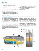
• 24 VDC multiphase detector with up to four (4) 4-20mA outputs for convenient control of top level, top of emulsion, water level, and sediment • Concurrent Top-Down and Bottom-Up signal generation • Level measurement not affected by changing media characteristics. • No need to move levels for calibration • 4-button keypad and graphic LCD display allow for convenient viewing of configuration parameters and echo curves • Proactive diagnostics advise not only what is wrong, but also offer troubleshooting tips. • Main electronics can be remote-mounted up to 30 m (100 feet) away from the probe. The...
Open the catalog to page 2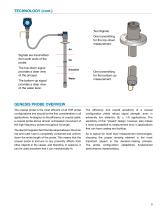
TECHNOLOGY (cont.) Two Signals One transmitting for the top-down measurement. Air Signals are transmitted from both ends of the probe. The top-down signal provides a clear view of the oil layer. The bottom-up signal provides a clear view of the water level. One transmitting for the bottom-up measurement. GENESIS PROBE OVERVIEW The coaxial probe is the most efficient of all TDR probe configurations and should be the first consideration in all applications. Analogous to the efficiency of coaxial cable, a coaxial probe allows almost unimpeded movement of the high frequency pulses throughout its...
Open the catalog to page 3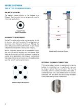
PROBE OVERVIEW TWO STYLES OF GENESIS PROBES ENLARGED COAXIAL The standard coaxial offering for the Genesis is an Enlarged diameter probe that can be generally used for most clean applications. Coaxial Probe Signal Propagation 5-CONDUCTOR PENTAROD With a PFA coated active center rod surrounded by four (4) reference rods, the 5-conductor Pentarod probe is an alternative probe offering for the Genesis. Although this probe still yields excellent performance, its open design makes it less susceptible to buildup and bridging. Both of the probes offered with the Genesis are unique, and each has specific...
Open the catalog to page 4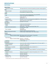
Initialization Time Less than 30 seconds © Pentarod probes must be used in metallic vessel or stillwell to maintain CE noise immunity
Open the catalog to page 5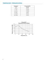
Temperature/Pressure Ratings
Open the catalog to page 6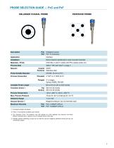
PENTAROD PROBE ENLARGED COAXIAL PROBE Description PxC Process Connection Threaded 3" NPT or 3" BSP (G 3") © 2nd digit E=English, M=Metric © Other o-ring materials available upon request. © Top Transition Zone: The detector may still operate but level readings may become non-linear. Bottom Transition Zone: Detector will not measure levels in this area. ® Genesis probes containing o-rings can be used for vacuum (negative pressure) service but are not hermetically sealed.
Open the catalog to page 7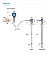
DIMENSIONS millimeters (inches) ∅ 34 (1.12) Flexible Conduit to Main Electronics Insertion Length Insertion Length Enlarged Coaxi
Open the catalog to page 8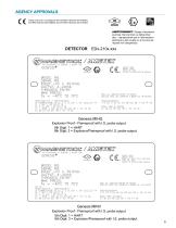
These units are in compliance with the EMC-directive 2014/30/EU, the PED-directive 2014/68/EU and the ATEX directive 2014/34/EU. AVERTISSEMENT! Danger d’explosion eventuel. Ne brancher ou debrancher des —equipements que si I’alimentation electrique a ete coupee ou si la zone est reputee non dangereuse. SINGLE SEAL MANUF YEAR: REFER TO INSTRUCTION MANUAL v—' OUTPUT: 4—20mA THREADED ENTRY: SEAL ALL CONDUITS WITHIN 18 INCHES SCELLEZ TOUS LES CONDUITS A MOINS DE 18 POUCES Explosion Proof - Flameproof with I.S. probe output 5th Digit: 1 = HART8th Digit: 3 = Explosion/Flameproof with I.S. probe output...
Open the catalog to page 9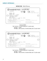
SINGLE SEAL MANUF YEAR: TYPE 4X, IP67 REFER TO INSTRUCTION FM21US0011X / FM21CA0007X IS CONNECTIONS TO CL I, II, III CL I, DIV 2, GP A,B,C,D T4 CL II, III DIV 1, GP E,F,G T4 CL I, ZONE 2 AEx ec [ia IIB Ga] IIC T4 Gc Ex ec [ia IIB Ga] IIC T4 Gc Non Incendive - Increased Safetywith I.S. probe output 5th Digit: 1 = HART SINGLE SEAL MANUF YEAR: MADE BY: 9240 ZELE, BELGIUM TYPE 4X, IP67 REFER TO INSTRUCTION MANUAL FM21US0011X / FM21CA0007X IS CONNECTIONS TO CL I, II, III CL I, DIV 2, GP A,B,C,D T4 CL II, III DIV 1, GP E.F.G T4 CL I, ZONE 2 AEx ec [ia IIB Ga] IIC T4 Gc Ex ec [ia IIB Ga] IIC T4 Gc Genesis...
Open the catalog to page 10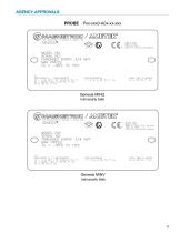
SINGLE SEAL MANUF YEAR: REFER TO INSTRUCTION MANUAL Intrinsically Safe 705 ENTERPRISE ST AURORA, IL 60504 USA SINGLE SEAL MANUF YEAR: MADE BY: 9240 ZELE, BELGIUM TYPE 4X, IP67 REFER TO INSTRUCTION MANUAL Genesis MINVIntrinsically Safe 11
Open the catalog to page 11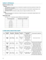
1. The flamepaths of the equipment are not intended to be repaired. Consult the manufacturer if repair of the flamepath joints is necessary.2. Refer to the manufacturer’s instructions to reduce the potential of an electrostatic charging hazard on the equipment enclosure.3. The detector shall be connected to a safety extra low-voltage circuit (SELV) with Um < 30VProbe:1. Refer to the manufacturer’s instructions to reduce the potential of an electrostatic charging hazard on the equipment enclosure.Temperature CodeFor Probe: T6...T1 temperature code are defined by the following table: Process Temperature...
Open the catalog to page 12All Magnetrol - AMETEK catalogs and technical brochures
 Echotel® Model 355
8 Pages
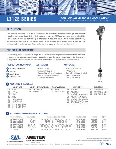 L312E SERIES
2 Pages
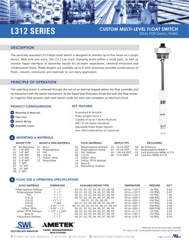 L312 SERIES
2 Pages
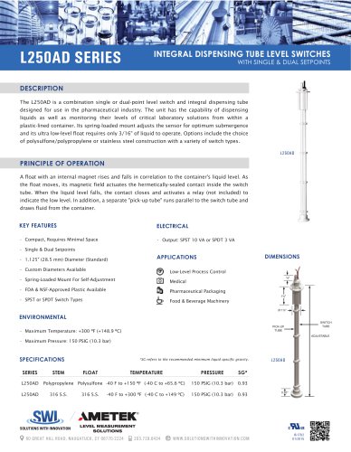 L250AD SERIES
1 Page
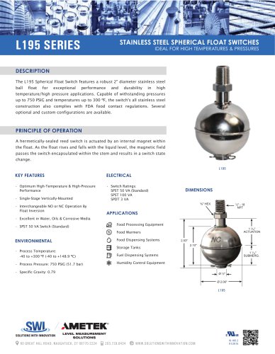 L195 SERIES
1 Page
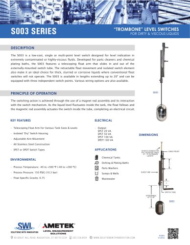 S003 series
1 Page
 JUPITER® Model JM4
20 Pages
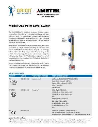 Model OES Point Level Switch
2 Pages
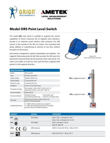 Model ORS Point Level Switch
2 Pages
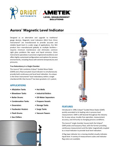 Aurora® Magnetic Level Indicator
28 Pages
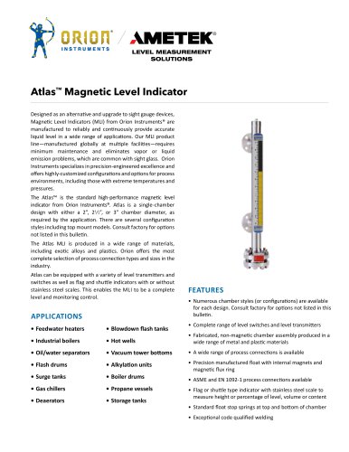 142_orion_atlas_mli
28 Pages
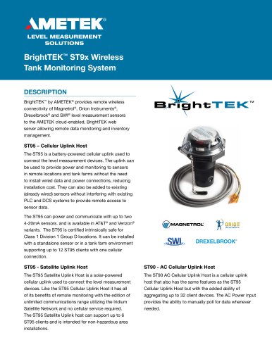 BrightTEK™ ST9x Wireless
12 Pages


Archived catalogs
 Product Line Quick Reference
8 Pages
 Crude Oil Processing
8 Pages
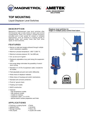
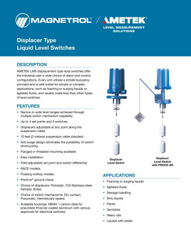
 Liquid Displacer Level Switches
16 Pages
 J Series Pneumatic Switch
8 Pages
 Series K Pneumatic Switch
8 Pages
 R Series High Temp Switch
12 Pages
 Ultrasonic Contact
4 Pages
 Thermal Dispersion
12 Pages
 Magnetic Level Indicators
12 Pages
 Guided Wave Radar
12 Pages
 Displacer Transmitters
4 Pages
 Water & Wastewater
12 Pages
 PULSAR ® R96
1 Page
 API 2350 Overfill Prevention
8 Pages
 Energy Management
4 Pages
 Flue Gas Desulferization
8 Pages
 APM Pneumatic Modulevel®
12 Pages
 Displacer Switches
20 Pages
 Floating Roof Detection
16 Pages
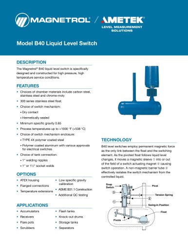 Model B40
12 Pages
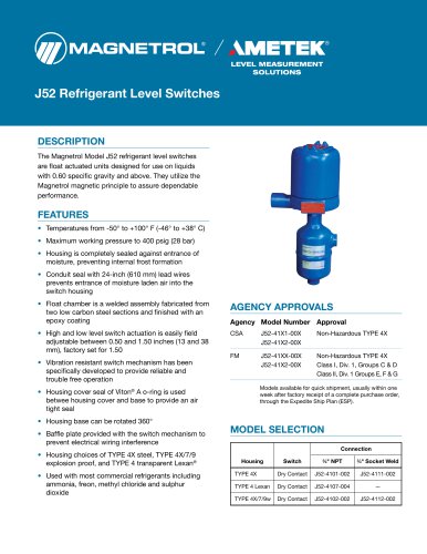 Model J52
2 Pages
 Series 3
24 Pages
 Series B73 and Series 75
12 Pages
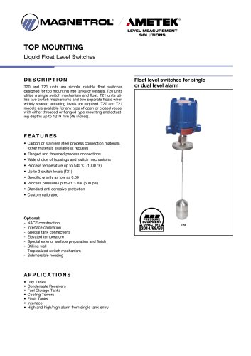 Models T20/T21
12 Pages
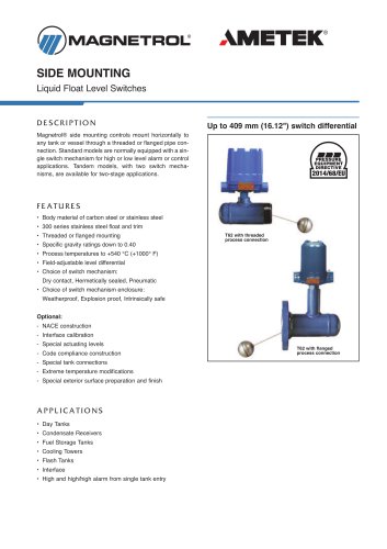 Models T5x & T6x
12 Pages
 Pneumatic Tuffy®
12 Pages
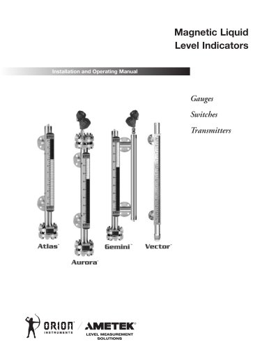 GEMINI™
20 Pages
 Ethylene Applications
8 Pages
 Heat Rate Awareness
8 Pages
 Mass Flow Measurement
12 Pages
 Seal Pots
4 Pages
 Petroleum Refining
16 Pages
 Power Generation
16 Pages
 INTERFACE IN THE FIELD
1 Page
 STEAM DRUM LEVEL MATTERS
1 Page
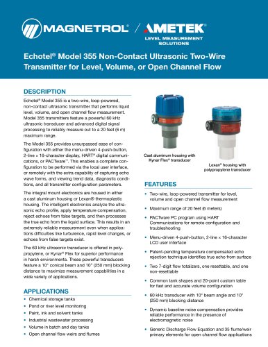 Echotel® 355
8 Pages
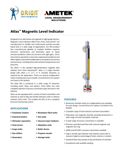 Atlas™ Magnetic Level Indicator
28 Pages
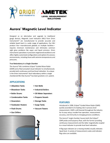 Aurora® Magnetic Level Indicator
28 Pages
 PRODUCT LINE CATALOGUE
106 Pages
 Emulsion In The Field
9 Pages
 Interface In The Field
14 Pages
 Natural Gas Processing
12 Pages
 Crude Oil Processing
8 Pages
 Thermatel® TD1/TD2
16 Pages
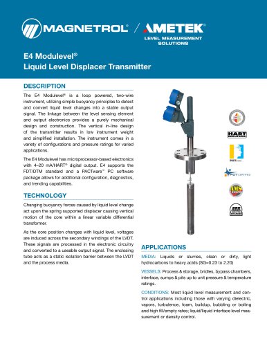
 E4 Modulevel®
12 Pages
 TUFFY® II
12 Pages
 Eclipse® 706 Hygienic
12 Pages












- MAGNETROL level switch
- MAGNETROL liquid level switch
- Level probe
- Liquid level sensor
- Measurement software
- Interface software
- MAGNETROL float level switch
- Analog level sensor
- MAGNETROL stainless steel level switch
- MAGNETROL level transmitter
- MAGNETROL liquid level transmitter
- Digital output level sensor
- MAGNETROL threaded level switch
- Vessel level sensor
- MAGNETROL analog level transmitter
- Liquids level gauge
- MAGNETROL tank level switch
- Flow sensor
- MAGNETROL magnetic float level switch
- Flow switch