
- Catalogs
- Magnetrol - AMETEK
- GEMINI™

GEMINI™
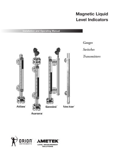
GEMINI™
- Notes: Offer additional information or clarification.
- Cautions: Warn users of conditions that could cause injury or equipment damage.
- Warnings: Indicate potentially dangerous situations that could result in serious injury or death.
- Follow standard procedures for servicing electrical equipment.
- Ensure power is off before connecting or disconnecting equipment to avoid explosion hazards.
- Mechanical level controls are warranted for three years, and electronic controls for eighteen months from the date of shipment.
- Warranty covers defects in materials or workmanship, excluding misapplication or consequential damages.
- Unpacking: Inspect for damage and verify contents against the packing slip.
- Pre-installation Checklist: Ensure the float is correctly placed and remove it before pressure testing.
- Equipment and Tools: Includes wrenches, screwdrivers, multimeters, and other necessary tools.
- Side Mount Installation: Ensure vertical alignment and proper piping to avoid liquid traps.
- Top Mount Installation: Requires correct vertical installation for proper float movement.
- Start-up: Increase pressure slowly and verify indicator accuracy.
- Insulation or Blanket Installation: Specifications for high and low-temperature insulation are provided.
- Steam Heat Tracing Installation: Instructions for connecting steam sources and checking for leaks.
- Electric Heat Tracing Installation: Details on configurations with thermostatic switches and wiring requirements.
- Description and Theory of Operation: Explains the function and operation of side and top mount MLIs.
- Troubleshooting: Provides guidance for addressing common issues.
- Spare Parts and Maintenance: Lists available spare parts and maintenance tips.
- Specifications: Detailed specifications for various models of switches and transmitters.
- Verify settings during installation and use appropriate wiring harness or junction box for field wiring.
- Use wire rated at +167 °F (+75 °C) and a minimum of 14 AWG for power and ground connections.
- Ensure housing is grounded via the protective ground screw.
- Follow applicable installation codes, especially in Class I, Division 1 locations with explosive gas mixtures.
- Use a GFI circuit breaker with a maximum 30 mA ground leakage current trip setting, sized at 125% of rated load.
- OES Cam Operated Switch: Used to expand control capabilities of magnetic level indicators. It is clamp-mounted and can be repositioned easily.
- ORS Electric Reed Switch: Explosion-proof and mounts via clamps, allowing repositioning without process disruption.
- For both OES and ORS switches, use wire rated at +167 °F (+75 °C) and ensure proper grounding.
- In hazardous areas, ensure the conduit is sealed and the enclosure cover is securely screwed down before powering the unit.
- OCT Reed Transmitter: Provides a 4–20 mA output signal proportional to liquid level and is pre-calibrated.
- Internal Electronic Transmitter: Installed in the Gemini MLI's secondary chamber, requires consultation with the factory for proper application.
- Eclipse Transmitter: Can be mounted in Gemini or Aurora MLIs, with specific probe types depending on the chamber design.
- Common issues include flags not rotating or rotating at incorrect heights, which may be due to float obstruction or incorrect specific gravity.
- Ensure the MLI is vertically level and check for magnetic particles causing drag on the float.
Catalog excerpts

Installation and Operating Manual LEVEL MEASUREMENT SOLUTIONS
Open the catalog to page 1
Read this Manual Before Installing This manual provides information on Magnetic Liquid Level Indicators. It is important that all instructions are read carefully and followed in sequence. Conventions Used in this Manual Certain conventions are used in this manual to convey specific types of information. General technical material, support data, and safety information are presented in narrative form. The following styles are used for notes, cautions, and warnings. Notes Notes contain information that augments or clarifies an operating step. Notes do not normally contain actions. They follow the...
Open the catalog to page 2
AMETEK* LEVEL MEASUREMENT SOLUTIONS 1.8.3.1 Units with a fixed-point 1.8.3.2 Units with an adjustable “bulb-type” 2.6.5 Model JM4 Jupiter® Magnetostrictive
Open the catalog to page 3
Caution: If equipment is used in a manner not specified by manufacturer, protection provided by equipment may be impaired. Unpack the instrument carefully. Inspect all units for damage. Report any concealed damage to carrier within 24 hours. Check the contents of the packing slip and purchase order. Check and record the serial number for future reference when ordering parts. Caution: Do not discard the shipping container until all parts are checked. 1. Float will be shipped outside the chamber unless otherwise noted. Place the float in chamber and manually move the float from 0% to 100% to 0%...
Open the catalog to page 4
Side Mount Installation Caution: This instrument is intended for use in Installation Category II, Pollution Degree 2 locations. NOTE: Top of gauge nameplates are available as an option. The MLI nameplate can be used as bottom reference of the external cage. Install the cage to the vessel with nameplate at bottom. Isolation valves are recommended for installation between vessel and external cage. Check to ensure the external cage is vertical. All piping should be straight and free of “low spots” or “pockets” so that the lower liquid connection will drain toward the external cage. Adjust piping...
Open the catalog to page 5
Caution: This instrument is intended for use in Installation Category II, Pollution Degree 2 locations. The top mount gauge can be installed as one complete unit or disassembled to allow access from inside the tank. Correct vertical installation is required to assure proper float movement. To disassemble you need only to unscrew the threaded cap at the bottom mounting flange or connection. Caution: Proper precautions should be taken to prevent the bending of the guide rod. Top/Bottom Connection Installation Caution: This instrument is intended for use in Installation Category II, Pollution Degree...
Open the catalog to page 6
Factory recommended high temperature insulation specifications: • Purpose: To maintain the required low temperature of the service fluid to be measured. • All insulation joints will be staggered. • All insulation joints will be sealed with a non-breathing moisture resistant mastic. • All weather resisting jacketing seams will be sealed with a weather resistant caulk. • The weather resistant jacket will be sealed to the 2" or 4" plexiglass frost extension, with weather resistant caulk. • The face of the frost extension must always be exposed. • Cryogenic units will be flipper style indicators.
Open the catalog to page 7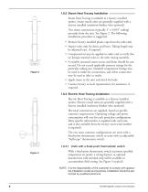
1.8.2 Steam Heat Tracing Installation Steam Heat Tracing is available as a factory installed option. Steam traced units are generally supplied with a factory installed insulation blanket (also optional). Two steam connections (typically 3⁄8" × 0.035" tubing) protrude from the unit. See Figure 2. The following installation procedure is suggested: • Remove factory installed plastic caps from the tube ends. • Inspect tube ends for dents and burrs. Tubing length may be adjusted (cut), if required. • Compressed air may be applied to either end to verify that no foreign material exists in the tube...
Open the catalog to page 8
1. Locate specific power specification and wiring diagram supplied with unit. 2. Provide appropriate conduit and wiring to the unit. 3. Apply sufficient operating power. 4. Verify that unit will generate sufficient heat and maintain proper temperature. NOTE: Wiring diagrams are supplied with units manufactured with this option. With an adjustable “bulb-type” thermostatic switch, the temperature may be preset at the factory, however field personnel should verify this setting during installation. A wiring harness, or optional junction box with terminal strip will be available to accommodate field...
Open the catalog to page 9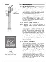
Switch Installation The Model OES snap switch is utilized to expand the control capabilities of Orion’s extensive line of magnetic level indicators. This cam-operated double pole double throw mechanism is clamp-mounted to the outside of the MLI. This mounting style allows easy addition or repositioning of switches without disruption of the process. The OES switch(es) are pre-installed, calibrated, and checked for proper orientation at the factory. Your unit may be equipped with one or more switches for alarming or control. To change the location of the switch in the field, simply unscrew the...
Open the catalog to page 10
The lower conduit opening is protected with a plastic shipping plug. The upper opening is sealed with a steel plug. If it is preferable to wire through the upper conduit entry, the steel plug may be moved to the lower opening. NOTE: For supply connections, use wire with a minimum rating of +167 ˚F (+75 ˚C) as required by the process conditions. Use a minimum of 14 AWG wire for power and ground field wires. NOTE: Housing must be grounded via protective ground screw in base of housing. NOTE: When using equipment in ambient temperatures above +158 °F (+70° C), cables used with the certified junction...
Open the catalog to page 11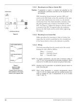
1.9.2.1 Mounting to an Atlas or Gemini MLI Caution: If equipment is used in a manner not specified by the manufacturer, protection provided by the equipment may be impaired. With mounting clamps loosened, position ORS reed switch on the MLI body so that the centerline of the stainless steel tube which houses the switch is at the desired switch point level. The switch should be oriented so that the green ground screw is closest to the bottom of the MLI. See Figure 6. Tighten the clamps so that the switch is secured to the MLI. If required, place the insulation between the MLI body and the switch...
Open the catalog to page 12All Magnetrol - AMETEK catalogs and technical brochures
 Echotel® Model 355
8 Pages
 L312E SERIES
2 Pages
 L312 SERIES
2 Pages
 L250AD SERIES
1 Page
 L195 SERIES
1 Page
 S003 series
1 Page
 JUPITER® Model JM4
20 Pages
 Model OES Point Level Switch
2 Pages
 Model ORS Point Level Switch
2 Pages
 Aurora® Magnetic Level Indicator
28 Pages
 142_orion_atlas_mli
28 Pages
 BrightTEK™ ST9x Wireless
12 Pages








Archived catalogs
 Product Line Quick Reference
8 Pages
 Crude Oil Processing
8 Pages
 Liquid Displacer Level Switches
16 Pages
 J Series Pneumatic Switch
8 Pages
 Series K Pneumatic Switch
8 Pages
 R Series High Temp Switch
12 Pages
 Ultrasonic Contact
4 Pages
 Thermal Dispersion
12 Pages
 Magnetic Level Indicators
12 Pages
 Guided Wave Radar
12 Pages
 Displacer Transmitters
4 Pages
 Water & Wastewater
12 Pages
 PULSAR ® R96
1 Page
 API 2350 Overfill Prevention
8 Pages
 Energy Management
4 Pages
 Flue Gas Desulferization
8 Pages
 APM Pneumatic Modulevel®
12 Pages
 Displacer Switches
20 Pages
 Floating Roof Detection
16 Pages
 Model B40
12 Pages
 Model J52
2 Pages
 Series 3
24 Pages
 Series B73 and Series 75
12 Pages
 Models T20/T21
12 Pages
 Models T5x & T6x
12 Pages
 Pneumatic Tuffy®
12 Pages
 Ethylene Applications
8 Pages
 Heat Rate Awareness
8 Pages
 Mass Flow Measurement
12 Pages
 Seal Pots
4 Pages
 Petroleum Refining
16 Pages
 Power Generation
16 Pages
 INTERFACE IN THE FIELD
1 Page
 STEAM DRUM LEVEL MATTERS
1 Page
 Echotel® 355
8 Pages
 Atlas™ Magnetic Level Indicator
28 Pages
 Aurora® Magnetic Level Indicator
28 Pages
 PRODUCT LINE CATALOGUE
106 Pages
 Emulsion In The Field
9 Pages
 Interface In The Field
14 Pages
 Natural Gas Processing
12 Pages
 Crude Oil Processing
8 Pages
 Thermatel® TD1/TD2
16 Pages
 E4 Modulevel®
12 Pages
 TUFFY® II
12 Pages
 Eclipse® 706 Hygienic
12 Pages





















- MAGNETROL level switch
- MAGNETROL liquid level switch
- Level probe
- Liquid level sensor
- Measurement software
- Interface software
- MAGNETROL float level switch
- Analog level sensor
- MAGNETROL stainless steel level switch
- MAGNETROL level transmitter
- MAGNETROL liquid level transmitter
- Digital output level sensor
- MAGNETROL threaded level switch
- Vessel level sensor
- MAGNETROL analog level transmitter
- Liquids level gauge
- MAGNETROL tank level switch
- Flow sensor
- MAGNETROL magnetic float level switch
- Flow switch