- Catalogs
- Magnetrol - AMETEK
- External Cage Displacer Actuated Liquid Level Switches
External Cage Displacer Actuated Liquid Level Switches
1 /16Pages

External Cage Displacer Actuated Liquid Level Switches
1 /16Pages
Catalog excerpts

External Cage Displacer Actuated Liquid Level Switches DESCRIPTION High Pressure Liquid Level Switches are displacer actuated units, utilizing a single switch mechanism for level alarm or control functions. These units are designed for service pressures up to 5000 psig (345 bar) and liquids with specific gravities of 0.40 and above. They utilize the Magnetrol® magnetic principle to assure dependable performance. FEATURES • Fabricated carbon steel cages are standard for all models. • B74 available with 304 & 316 SS cages • Sealed or flanged cages available • Inconel displacer spring and stainless steel trim • Stainless steel displacers • Pressures to 5000 psig (345 bar) • Temperatures to +750° F (+399° C) • Specific gravity down to 0.40 • Choice of switch mechanism: Dry contact Pneumatic Hermetically sealed • Choice of switch enclosure: NEMA 1 carbon steel for pneumatics TYPE 4X/7/9 Class I, Div. 1, Groups C & D polymer coated aluminum TYPE 4X/7/9 Class I, Div. 1, Group B polymer coated aluminum • Choice of tank connections: NPT Socketweld Side/side flanges Side/bottom flanges Model C74 Flanged External Cage with TYPE 4X/7/9 Switch Housing APPLICATIONS • Hydraulic accumulators • Hydrocarbon flash tanks • H.P. scrubbers • Optional custom high temperature insulation available. See bulletin 41-106 for details.
Open the catalog to page 1
OPTIONS • Special levels/body extensions • Gold switch contacts • Vent and drain connections TECHNOLOGY The weight of the displacer ➀ is supported by the spring ➁. Rising liquid level imparts buoyancy forces on the displacer allowing the spring to compress. The attraction sleeve ➂, attached to the spring, moves upward into the field of a permanent magnet ➃. Magnet motion causes the switch ➄ to actuate. A non-magnetic barrier tube ≈ provides a static pressure boundary between the switch mechanism and the displacer assembly. SPECIFICATIONS SWITCH SERIES J & K PNEUMATIC SWITCHES SERIES F, HS, H1...
Open the catalog to page 2
APPROVED MODEL AREA CLASSIFICATION All with an electric switch mechanism and a housing listed as TYPE 4X/7/9 Class I, Div 1, Groups C & D Class II, Div 1, Groups E, F & G All with an electric switch mechanism and a housing listed as TYPE 4X/7/9 Class I, Div 1, Group B Class I, Div 1, Groups B, C & D Class II, Div 1, Groups E, F & G All with a Series F, H1, HS or 8 electric switch mechanism and a housing listed as CSA TYPE 4X All with an electric switch mechanism and a housing listed as TYPE 4X/7/9 Class I, Div 1, Groups C & D Class II, Div 1, Groups E, F & G All with an electric switch mechanism...
Open the catalog to page 3
ACTUATION SEALED INCHES Sealed Chamber w/NPT or Socket weld Side/Bottom Connections (B74, H13, H31, H51) Sealed Chamber w/NPT or Socket weld Side/Side Connections (H13, H31, H51) Sealed Chamber Side/Side Flange Connections (B74 only) Sealed Chamber Side/Side Flange Connections (H13, H31, H51) Sealed Chamber Side/Bottom Flange Connections (B74, H13, H31, H51)
Open the catalog to page 4
ACTUATION SEALED INCHES Model Code
Open the catalog to page 5
DIMENSIONAL SEALED INCHES Rotation clearance Bottom connection Sealed Chamber w/NPT or Socket weld Side/Bottom Connections (B74, H13, H31, H51) Sealed Chamber w/NPT or Socket weld Side/Side Connections (H13, H31, H51) Sealed Chamber Side/Side Flange Connections (B74 only) Sealed Chamber Side/Bottom Flange Connections (B74, H13, H31, H51) Sealed Chamber Side/Side Flange Connections (H13, H31, H51) Electric Switches: Pneumatic Switches: NEMA 1: TYPE 4X/7/9* TYPE 4X/7/9 Group B* * These dimensions increase by 2.19 (56) when used with Series HS switches with terminal blocks.
Open the catalog to page 6
DIMENSIONAL SEALED INCHES Dimensions –Upper Side/Bottom NPT or SW Model Connection Code Size Dimensions –Side/Side Model Connection Code Size
Open the catalog to page 7
ACTUATION FLANGED INCHES Flanged Top Chamber w/NPT or Socket weld Side/Bottom Connections (C74, H15, H32, H52) Flanged Top Chamber w/NPT or Socket weld Side/Side Connections (H15, H32, H52) HL LL Flanged Top Chamber Side/Side Flange Connections (C74 only) Flanged Top Chamber Side/Bottom Flange Connections (C74, H15, H32, H52) Flanged Top Chamber Side/Side Flange Connections (H15, H32, H52)
Open the catalog to page 8
ACTUATION FLANGED INCHES Model Code
Open the catalog to page 9
DIMENSIONAL FLANGED INCHES Flanged Top Chamber w/NPT or Socket weld Side/Bottom Connections (C74, H15, H32, H52) Flanged Top Chamber w/NPT or Socket weld Side/Side Connections (H15, H32, H52) Flanged Top Chamber Side/Side Flange Connections (C74 only) HL C Flanged Top Chamber Side/Bottom Flange Connections (C74, H15, H32, H52) Flanged Top Chamber Side/Side Flange Connections (H15, H32, H52) Electric Switches: Pneumatic Switches: NEMA 1: TYPE 4X/7/9* TYPE 4X/7/9 Group B* * These dimensions increase by 2.19 (56) when used with Series HS switches with terminal blocks.
Open the catalog to page 10
DIMENSIONAL FLANGED INCHES Dimensions –Upper Side/Bottom NPT or SW Model Connection Code Size Dimensions –Side/Side Model Connection Code Size
Open the catalog to page 11
Models available for quick shipment, usually within one week after factory receipt of a complete purchase order, through the Expedite Ship Plan (ESP). SPECIFIC GRAVITY AND PRESSURE RATING CODE Cage Style Cage Material Carbon Steel Carbon Steel 300# Carbon steel Flanged Carbon steel Minimum Specific Gravity Up to Temperature Shown Model Spring Trim Inconel & 316 SS 316 SS Inconel & 316 SS Inconel & 316 SS Inconel & 316 SS Cage Carbon Steel Carbon Steel Carbon Steel 304 Stainless Steel 316 Stainless Steel TANK CONNECTION TYPE AND SIZE B74 1" 1 ⁄2" 1 Connection Type NPT Socketweld 150 lb ANSI flanges...
Open the catalog to page 12
ELECTRIC SWITCH MECHANISM AND ENCLOSURE ➂ TYPE 4X/7/9 Aluminum Enclosure Maximum Process ➄ Temperature ° F (° C) Series B Snap Switch Series C Snap Switch SPDT DPDT SPDT DPDT Series D Snap Switch for DC Current Application SPDT DPDT Series F Hermetically Sealed Snap Switch SPDT DPDT SPDT DPDT SPDT DPDT SPDT DPDT Series HS 5 Amp Hermetically ≈ Sealed Snap Switch w/Wiring Leads Series HS 5 Amp Hermetically ≈ Sealed Snap Switch w/Terminal Block Series 8 Hermetically Sealed Snap Switch PNEUMATIC SWITCH MECHANISM AND ENCLOSURE Switch Description Maximum Supply Pressure Bleed Type Maximum Process Temperature...
Open the catalog to page 13All Magnetrol - AMETEK catalogs and technical brochures
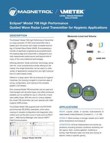 Eclipse® 706 Hygienic
12 Pages
 TUFFY® II
12 Pages
 E4 Modulevel®
12 Pages
 Thermatel® TD1/TD2
16 Pages
 Crude Oil Processing
8 Pages
 Natural Gas Processing
12 Pages
 Interface In The Field
14 Pages
 Emulsion In The Field
9 Pages
 PRODUCT LINE CATALOGUE
106 Pages
 Aurora® Magnetic Level Indicator
28 Pages
 Atlas™ Magnetic Level Indicator
24 Pages
 Echotel® 355
4 Pages
 STEAM DRUM LEVEL MATTERS
1 Page
 INTERFACE IN THE FIELD
1 Page
 Power Generation
16 Pages
 Petroleum Refining
16 Pages
 Seal Pots
4 Pages
 Mass Flow Measurement
12 Pages
 Heat Rate Awareness
8 Pages
 Ethylene Applications
8 Pages
 GEMINI™
32 Pages
 Pneumatic Tuffy®
12 Pages
 Models T5x & T6x
8 Pages
 Models T20/T21
12 Pages
 Series B73 and Series 75
12 Pages
 Series 3
24 Pages
 Model J52
2 Pages
 Model B40
4 Pages
 Floating Roof Detection
16 Pages
 Displacer Switches
20 Pages
 APM Pneumatic Modulevel®
12 Pages
 Flue Gas Desulferization
8 Pages
 Energy Management
4 Pages
 API 2350 Overfill Prevention
8 Pages
 PULSAR ® R96
1 Page
 Water & Wastewater
12 Pages
 Displacer Transmitters
4 Pages
 Guided Wave Radar
12 Pages
 Magnetic Level Indicators
12 Pages
 Thermal Dispersion
12 Pages
 Ultrasonic Contact
4 Pages
 R Series High Temp Switch
12 Pages
 Series K Pneumatic Switch
8 Pages
 J Series Pneumatic Switch
8 Pages
 Liquid Displacer Level Switches
16 Pages
 Crude Oil Processing
8 Pages
 Product Line Quick Reference
8 Pages


- Level probe
- Liquid level sensor
- Interface software
- Measurement software
- MAGNETROL float level switch
- Analog level sensor
- MAGNETROL stainless steel level switch
- MAGNETROL level transmitter
- MAGNETROL liquid level transmitter
- Digital output level sensor
- MAGNETROL threaded level switch
- Vessel level sensor
- MAGNETROL analog level transmitter
- Liquids level gauge
- MAGNETROL tank level switch
- Flow sensor
- MAGNETROL magnetic float level switch
- Flow switch