
- Catalogs
- Magnetrol - AMETEK
- Aurora® Magnetic Level Indicator

Aurora® Magnetic Level Indicator
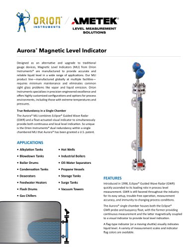
Aurora® Magnetic Level Indicator
Orion Instruments' Magnetic Level Indicators (MLI) are advanced devices designed to replace traditional gauge devices, providing accurate and reliable liquid level measurement with minimal maintenance. They are customizable for extreme temperatures and pressures, addressing common issues like vapor and liquid emission.
The Aurora® MLI integrates Eclipse® Guided Wave Radar (GWR) with a float-actuated visual indicator, offering both continuous and local level indication. This patented dual redundancy is a significant feature.
MLIs are applicable in various industrial settings, including alkylation tanks, boiler drums, oil-water separators, and storage tanks, among others.
The Eclipse® Model 706 High Performance Transmitter utilizes Guided Wave Radar technology, supporting various standards and offering enhanced reliability and safety certifications.
- Design: Single chamber
- Materials: Metal alloys, plastics, 316 stainless steel
- Pressure Ratings: ASME 150# to 2500#, EN PN16 to PN320
- Temperature Range: -196 to +538 °C (-320 to +1000 °F)
- Visual Indicators: Magnetically actuated flag assembly
- Approvals: Industrial, ATEX, NACE, ASME code construction
- High-temperature and cryogenic insulation options
- Magnetic Particle Traps
- Heat tracing for freeze protection
Orion Instruments' MLIs provide a robust solution for liquid level measurement, with advanced features and customization options for various industrial applications.
- Voltage: 250 VAC/150 VDC max.
- Maximum Dead Band: ±0.75" or ±0.50" float travel
- Temperature Range: -58 to +250 °F (-50 to +121 °C) without insulation; up to 500 °F (260 °C) with insulation
- Enclosure Material: Cast aluminum or stainless steel
- Model OES
- Model ORS
Model ORS: Position and secure the switch on the MLI body, ensuring proper grounding and wiring.
Model OES: Position and secure the switch, ensuring the internal mechanism is correctly oriented and wired.
- Chamber Construction: Various stainless steel grades, titanium, Monel®, Hastelloy C-276, Alloy 20, Inconel® 625, Incoloy® 825, 254 SMO
- Flange Ratings: ASME and EN standards
- Process Connection Types: Threaded, socket weld, slip-on flange, weld neck flange
- Insulation Options
- Indicator Housing Material
- Gasket Styles
- Bolting Material
Various units and scales are available, with specific conditions requiring aluminum indicators with glass windows for high temperatures.
Float codes specify metallic construction types for different pressure and temperature ratings.
Chamber codes and float materials are specified, with titanium as the default for certain applications.
Instructions for specifying visual indication lengths are provided.
Details on model number, material, and construction grade, with design pressures for various materials.
Descriptions of the Jupiter magnetostrictive transmitter and OCT reed chain transmitter, including mounting options.
Information on OES and ORS level switches, including mounting options and dimensions.
Details on the Eclipse transmitter model, power options, signal output, and accessories.
Various housing and safety options are available, including explosion-proof and intrinsically safe designs.
Options for general purpose, intrinsically safe, explosion-proof, and other safety classifications.
Details on conduit connection dimensions and classifications.
Specifications for probe types, applications, and conditions, including temperature and pressure ranges.
Details on model numbers, probe types, and construction options.
Specifications for the Magnetrol Eclipse GWR level transmitter used in Aurora MLI, including probe selection and special requests.
Bulletin: ORI-143.4
Effective: August 2022
Supersedes: March 2021
Contact: ametek-measurement.com
Catalog excerpts

AMETEK® LEVEL MEASUREMENT SOLUTIONS • Industrial Boilers • Oil-Water Separators • Propane Vessels • Storage Tanks • Surge Tanks • Vacuum Towers Designed as an alternative and upgrade to traditional gauge devices, Magnetic Level Indicators (MLI) from Orion Instruments® are manufactured to provide accurate and reliable liquid level in a wide range of applications. Our MLI product line-manufactured globally at multiple facilities— requires minimum maintenance and eliminates common sight glass problems like vapor and liquid emission. Orion Instruments specializes in precision-engineered excellence and offers highly customized configurations and options for process environments, including those with extreme temperatures and pressures. True Redundancy in a Single Chamber The Aurora® MLI combines Eclipse® Guided Wave Radar (GWR) and a float-actuated visual indicator to simultaneously provide both continuous and local level indication. So unique is the Orion Instruments® dual redundancy within a single chambered MLI that Aurora® has been granted a U.S. patent. • Alkylation Tanks • Blowdown Tanks • Boiler Drums • Condensation Tanks • Feedwater Heaters • Flash Drums Introduced in 1998, Eclipse® Guided Wave Radar (GWR) quickly ascended to its leading role in process level measurement. GWR is still favored throughout the industry for its easy setup, trouble-free operation, measurement accuracy, and immunity to changing process conditions. The Aurora® single chamber houses both the Eclipse® GWR probe and buoyancy float, with the former providing continuous measurement and the latter magnetically coupled to a visual indicator to provide local level indication. A flag-type indicator (or a moving shuttle) visually indicates liquid level. A variety of measurement scales and indicator flag colors
Open the catalog to page 1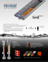
1 InstaSeal™ valve allows for an effective vacuum seal 2 Double custom D-ring end plug ensures a reliable seal that keeps moisture out 3 All-metal high contrast powder coated or anodized flags are wider to enhance overall visibility 4 Robust 316 stainless steel enclosure designed to face the elements * 5 Extruded shatter-resistant viewing window enhances visibility and allows the flags to position closely to the float, enhancing the magnetic coupling viewing angle Single Scale Scale Options: • Inches / Feet • Running Inches • Millimeters / Meters • Centimeters / Meters The patented REVEAL™ indicator...
Open the catalog to page 2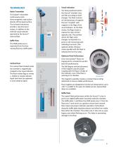
TECHNOLOGY Radar Transmitter Baffle Plate The GWR probe area is separated from the freemoving float by a baffle plate. The float positioned within the Aurora® chamber rises and falls according to level changes. The float contains an internal group of magnets that are “coupled” with magnets in the flags of the visual indicator. As the float moves, the flags rotate to expose the color of their opposite side. The position where the flag’s color changes corresponds to a point on the measuring scale indicating true level. (The optional shuttle indicator moves parallel with the float to indicate level...
Open the catalog to page 3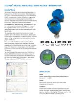
ECLIPSE® MODEL 706 GUIDED WAVE RADAR TRANSMITTER DESCRIPTION The Eclipse® Model 706 High Performance Transmitter is a loop-powered, 24 VDC level transmitter that is based upon the proven and accepted technology of Guided Wave Radar (GWR). Encompassing a number of significant engineering accomplishments, this leading edge level transmitter is designed to provide measurement performance well beyond that of many of the more traditional technologies. Utilizing patented “diode switching” technology, along with the most comprehensive probe offering on the market, this single transmitter can be used...
Open the catalog to page 4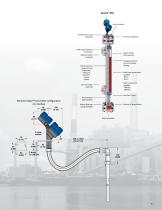
Vent connection Top float stop spring (standard) Wide range of process connections Flag or shuttle style indicators High level switch (optional) Anodized aluminum or 316 SS indicator housing 316 SS scale for a variety of units: feet/inches meters/cm percent % volume custom ASME code construction available: B31.1 B31.3 NACE Construction available: MR0103 MR0175 Low level switch (optional) Remote Eclipse® Transmitter Configuration mm (inches) 86 (3.38) Insta-Seal™ valve Broad range of alloy chambers Bottom float stop spring (standard) Drain Connection
Open the catalog to page 5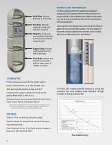
ORION FLOAT TECHNOLOGY Weld Ring: Secures float cap to main body Flux Ring: Absorbs magnetic energy and directs it outward Magnets: A full array surrounds the float with a strong and consistent magnetic field The float contained within the magnetic level indicator is perhaps the most important element of the instrument. Its structural design, volume displacement, weight, and buoyancy force are all carefully considered when a float is specified for a particular application. Orion engineers have designed and tested hundreds of floats to gather the most accurate data available. We have designs for...
Open the catalog to page 6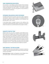
HIGH-TEMPERATURE INSULATION Orion specializes in custom fiberglass insulation blankets for MLIs of all shapes and sizes. They are constructed with high-quality materials capable of constant contact with temperatures up to 538 °C (1000 °F). This insulation is available as personnel protection or with heat tracing options for freeze protection or process temperature maintenance. CRYOGENIC INSULATION & FROST EXTENSION To facilitate operation where the product is kept cold via chillers, refrigerants, and condensers, cryogenic insulation is provided. By insulating the MLI with a specialized cryogenic...
Open the catalog to page 8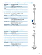
Jupiter Model JM4 on Aurora® OCT REED CHAIN TRANSMITTER SPECIFICATIONS Measuring Range: Mounting Arrangement: External mount probe with integral top or bottom mounted electronics
Open the catalog to page 9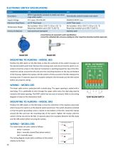
Maximum Dead Band: ±0.75" float travel ±0.50" float travel empera ure ange: Requiring insulation up to 500 °F (260 °C) Requiring insulation up to 500 °F (260 °C) Enclosure Material: Cast aluminum (standard) Stainless steel Consult factory for pneumatic switch specifications. Consult the individual MLI accessory catalogs for their respective hazardous location approvals. Position the OES switch on the MLI body so that the centerline of the switch housing is at the desired switch point level. Remove the housing cover and ensure that the switch is oriented so that the arrow on the internal mechanism...
Open the catalog to page 10All Magnetrol - AMETEK catalogs and technical brochures
 Echotel® Model 355
8 Pages
 L312E SERIES
2 Pages
 L312 SERIES
2 Pages
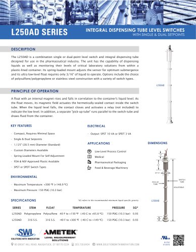 L250AD SERIES
1 Page
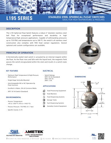 L195 SERIES
1 Page
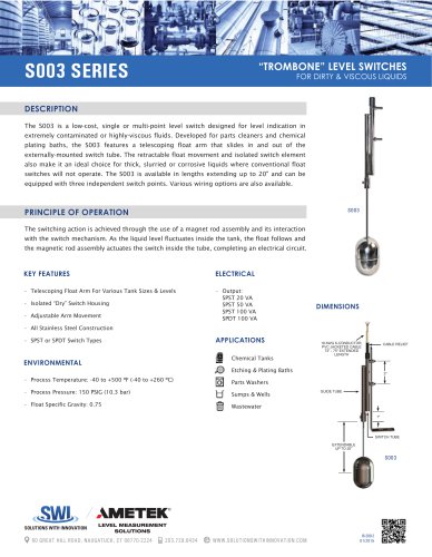 S003 series
1 Page
 JUPITER® Model JM4
20 Pages
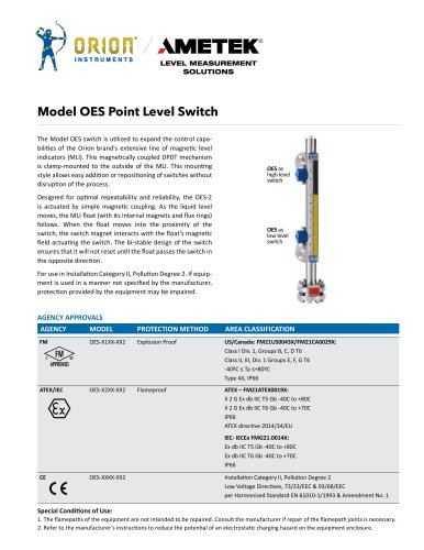 Model OES Point Level Switch
2 Pages
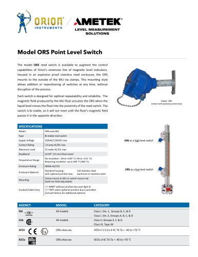 Model ORS Point Level Switch
2 Pages
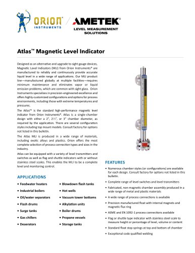 142_orion_atlas_mli
28 Pages
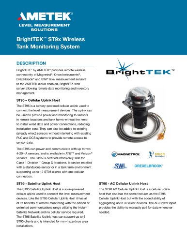 BrightTEK™ ST9x Wireless
12 Pages
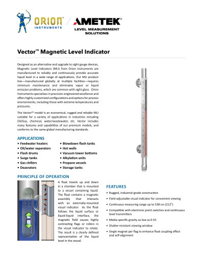

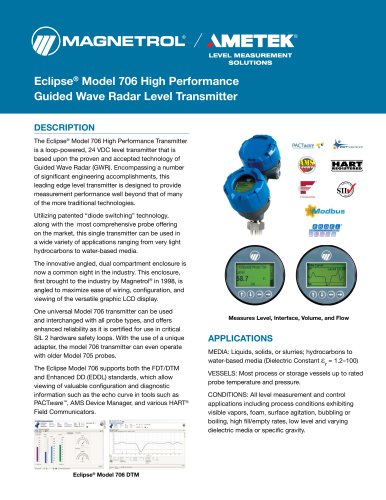
Archived catalogs
 Product Line Quick Reference
8 Pages
 Crude Oil Processing
8 Pages
 Liquid Displacer Level Switches
16 Pages
 J Series Pneumatic Switch
8 Pages
 Series K Pneumatic Switch
8 Pages
 R Series High Temp Switch
12 Pages
 Ultrasonic Contact
4 Pages
 Thermal Dispersion
12 Pages
 Magnetic Level Indicators
12 Pages
 Guided Wave Radar
12 Pages
 Displacer Transmitters
4 Pages
 Water & Wastewater
12 Pages
 PULSAR ® R96
1 Page
 API 2350 Overfill Prevention
8 Pages
 Energy Management
4 Pages
 Flue Gas Desulferization
8 Pages
 APM Pneumatic Modulevel®
12 Pages
 Displacer Switches
20 Pages
 Floating Roof Detection
16 Pages
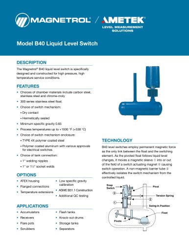 Model B40
12 Pages
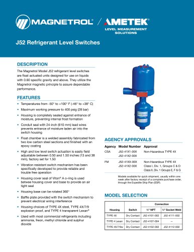 Model J52
2 Pages
 Series 3
24 Pages
 Series B73 and Series 75
12 Pages
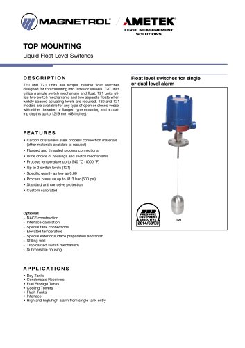 Models T20/T21
12 Pages
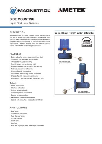 Models T5x & T6x
12 Pages
 Pneumatic Tuffy®
12 Pages
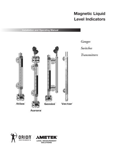 GEMINI™
20 Pages
 Ethylene Applications
8 Pages
 Heat Rate Awareness
8 Pages
 Mass Flow Measurement
12 Pages
 Seal Pots
4 Pages
 Petroleum Refining
16 Pages
 Power Generation
16 Pages
 INTERFACE IN THE FIELD
1 Page
 STEAM DRUM LEVEL MATTERS
1 Page
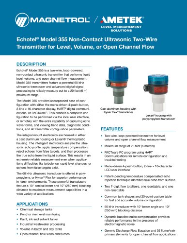 Echotel® 355
8 Pages
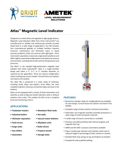 Atlas™ Magnetic Level Indicator
28 Pages
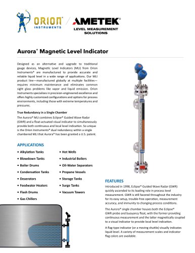 Aurora® Magnetic Level Indicator
28 Pages
 PRODUCT LINE CATALOGUE
106 Pages
 Emulsion In The Field
9 Pages
 Interface In The Field
14 Pages
 Natural Gas Processing
12 Pages
 Crude Oil Processing
8 Pages
 Thermatel® TD1/TD2
16 Pages
 E4 Modulevel®
12 Pages
 TUFFY® II
12 Pages
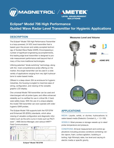 Eclipse® 706 Hygienic
12 Pages


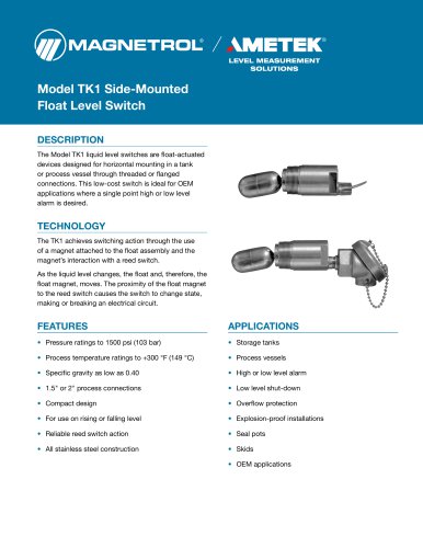








- MAGNETROL liquid level switch
- Level probe
- Liquid level sensor
- Measurement software
- Interface software
- MAGNETROL float level switch
- Analog level sensor
- MAGNETROL stainless steel level switch
- MAGNETROL liquid level transmitter
- Digital output level sensor
- MAGNETROL threaded level switch
- Vessel level sensor
- MAGNETROL analog level transmitter
- Liquids level gauge
- MAGNETROL tank level switch
- Flow sensor
- MAGNETROL magnetic float level switch
- Flow switch