
- Catalogs
- Madell Technology
- CA4810A Curve Tracer

- Products
- Catalogs
- News & Trends
- Exhibitions
CA4810A Curve Tracer

CA4810A Curve Tracer
- Vertical Axis Deflection: Collector current (Ic) ranges from 2µA/DIV to 1A/DIV with 15 steps and ±3% accuracy. Base current or voltage is 20mV/DIV with ±3% accuracy.
- Horizontal Axis Deflection: Collector voltage ranges from 0.05V/DIV to 50V/DIV with 10 steps and ±3% accuracy.
- Step Signals: Step current ranges from 1µA to 0.1A with 16 steps and ±5% accuracy. Step voltage ranges from 0.05V to 2V with 6 steps and ±5% accuracy.
- Collector Sweeping Supply: Maximum sweeping current varies with voltage, e.g., 10A at 0-5V.
- Physical: Desktop device with dimensions 510 x 251 x 341mm, weight 13.5kg, and operates at 110V±10%, 60Hz±5%.
- Collector AC/DC Switch: Allows selection between AC and DC voltage applications.
- Max Peak Volts: Adjusts maximum collector peak voltages in four steps.
- INV: Adjusts polarity of collector voltage for NPN or PNP transistors.
- Series Resistors: Used for dissipation limit in the collector measurement loop.
- Looping and Compensation: Reduce capacitive current errors.
- 3.1 Introduction: Proper switch settings are crucial to avoid damage to the device. Initial settings should be conservative, with adjustments made according to test conditions.
- 3.2 Measurement Examples: Provides detailed settings and procedures for measuring various components, including NPN transistors, diodes, and field-effect transistors. Examples include output curves, HFE measurement, and reversal breakdown voltage tests.
Catalog excerpts

CA4810A Curve Tracer User’s Manual Madell Technology Corporation http://www.madelltech.com Copyright
Open the catalog to page 1
CA4810A curve tracer is an instrument which can be used to view transistor and diode feature curves. It can also be used to measure their low frequency static-state characters, as well as other semiconductor and circuit measurements. 1. Specifications: 1.1 Vertical Axis Deflection Collector voltage (Ic): 2|j.A/DIV~1A/DIV, 15 steps, accuracy ± 3% Reversal drain current (Ir): 0.2 pA/DIV~ 1A/DIV, 6 steps Accuracy: 2pA/DIV~ 10uA/DIV, ±3& 0.2pA/DIV~1uA/DIV, ±10% 0.2|jA/DIV, interfere < 0.5V/DIV Base current or base voltage: 20mV/DIV, accuracy ±3% Deflection multiplying factor: x 0.5, accuracy ±10%...
Open the catalog to page 2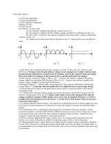
Front panel controls: (1) CRT focus adjustment. (2) Trace tilt adjustment. (3) CRT brightness adjustment. (4)Power on LED. (5) Power switch. (6) Collector AC/DC switch: AC: the collector is applied with alternate voltage (see fig. 2.3); DC: the collector is applied with DC pulsating voltage, rectified but not filtered (see fig. 2.4); DC and “I/DIV” switch at IR, the collector is applied with continuous DC voltage, rectified and filtered (see fig. 2.5); AC voltage can be used to show the forward and reverse C-V characteristic curves for bilateral diode. (7) Max Peak Volts: maximum collector peak...
Open the catalog to page 5
(17) Step polarity switch: the step output is at positive polarity at “+” position and negative at “-“ position. (18) STEP/OFFSET AMPL switch: this switch serves two functions: a. Base current source from 1µA/STAGE to 0.1A/STAGE, in 16 steps. b. Base voltage source from 0.05V/STAGE to 2V/STAGE, in 6 steps. (19) Offset: Adjust this knob to cover any position between stages. It should be set at the zero level to measure amplifying multiples. (20) Number of steps: continuously adjust the step of every cluster from 4 to 10 stages, (21) Horizontal position: to adjust the horizontal position of the...
Open the catalog to page 6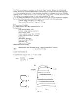
3.1.2 When measuring power transistors, set the step at “Single” position. Increase the collector peak voltage, decrease the dissipation limit resistance or increase the step current to find the proper test values. 3.1.3 When measuring the reversal voltage, maximum dissipation limit resistance must be used (500kQ or 1000kQ); Set the collector current to Ir, and increase the peak voltage slowly to reach the breakdown point; The IR feature is a continuous curve at AC mode, and it is a point at DC mode. 3.1.4 The double cluster function is mainly used to test the conjugation of current amplification...
Open the catalog to page 7
3.2.2 Hfe measurement of NPN 9013 transistor (see Fig. 3-2) Testing settings: Peak collector voltage: 0~5V Collector voltage polarity: positive (+) Series resistors: 250Q X axis: collector voltage (Vce): 0.5V/DIV Y axis: collector current (Ic): 1mA/DIV Step: Repeat Step polarity: positive (+) Step choice: 5|jA/STAGE Step offset: zero Stage number: 10 stages The following curves in Fig. 3-2 are obtained by turning the X axis horizontal switch anticlockwise to the end. Voltage amplification multiple: shown division of nth vertical line on Y axis x Current/DIV (27) value Ic HFE = n x step switch...
Open the catalog to page 8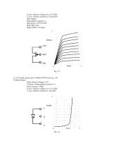
X axis: collector voltage (Vce): 0.5V/DIV Y axis: collector current (Ic): 0.5mA/DIV Step: Repeat Step polarity: negative (-) Step choice: 0.2V/STAGE Step offset: zero Stage number: 10 stages Fig. 3-3 3.2.4 Forward current curve of diode IN4148 (see Fig. 3-4) Testing settings: Peak collector voltage: 0~5V Collector voltage polarity: positive (+) Series resistors: 250Ω X axis: collector voltage (Vce): 0.1V/DIV Y axis: collector current (Ic): 1mA/DIV
Open the catalog to page 9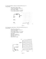
3.2.5 Reversal breakdown voltage test of diode IN4148 (see Fig. 3-5) Testing settings: Peak collector voltage: 0~500V Collector voltage polarity: positive (+) Series resistors: 100KΩ X axis: collector voltage (Vce): 20V/DIV Y axis: collector current (Ic): 1µA/DIV Fig.3-5 3.2.6 Common base output feature of NPN 9013 transistor (see Fig. 3-6) Testing settings: Peak collector voltage: 0~5V Collector voltage polarity: positive (+) Series resistors: 250Ω X axis: collector voltage (Vce): 0.5V/DIV Y axis: collector current (Ic): 1mA/DIV Step: Repeat Step polarity: negative (-) Step choice: 0.1mA/STAGE...
Open the catalog to page 10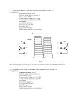
3.2.7 Double cluster display of NPN 9013 transistor output features (see Fig. 3-7) Testing settings: Peak collector voltage: 0~5V Collector voltage polarity: positive (+) Series resistors: 250Q X axis: collector voltage (Vce): 1V/DIV Y axis: collector current (Ic): 1mA/DIV Step: Repeat Step polarity: positive (+) Step choice: 5pA/STAGE Step offset: zero Stage number: 10 stages Double cluster selected on the test fixture. Note: the trace separation knob (22) can be used to move the two clusters closer for better observations. 3.2.8 Switching character of high cut-in voltage VMOS transistor IRF840...
Open the catalog to page 11All Madell Technology catalogs and technical brochures
 MADELL QK870
4 Pages
 MADELL QK857D
5 Pages
 Frequency counter series
3 Pages

- Power supply unit
- Kiln
- DC power supply
- AC/DC power supply
- Tabletop power supply
- Generator
- Multimeter
- Variable-output power supply
- Laboratory power supply
- Digital multimeter
- Screen printing machine
- Portable multimeter
- Automatic kiln
- Multiple-output power supply
- Automatic screen printing machine
- Cutting and stripping machine
- Industrial multimeter
- Cable stripping machine
- Soldering machine
- Oscilloscope