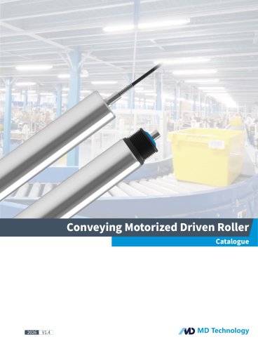
- Catalogs
- M&D (Motor and Drive)
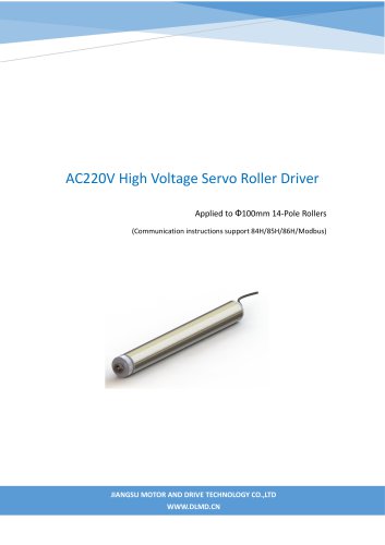
- Specification of MDB-F Infrared Photoelectric Servo Drive V1.2(NCBS Roller Drive)
Specification of MDB-F Infrared Photoelectric Servo Drive V1.2(NCBS Roller Drive)
1 /12Pages
Specification of MDB-F Infrared Photoelectric Servo Drive V1.2(NCBS Roller Drive)
1 /12Pages
Catalog excerpts
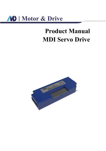
Motor & Drive Product Manual MDB Infrared Photoelectric Servo Driver F Series for Cross-Belt / Linear Sorter / AGV
Open the catalog to page 1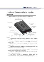
Motor & Drive 1.Infrared Photoelectric Driver Interface Definition 1.1Infrared Photoelectric Driver Interface Definition Figure 1-1 Schematic Diagram of Infrared Photoelectric Driver Interface Definition Remarks: ①Power Interface: Connect DC+ to power supply 48V+, and DC- to power supply 48V-; ②Motor UVW Interface: Connect to the white 6P plug of the electric roller outgoing cable; ③Encoder Interface: Connect to the white 8P plug of the electric roller outgoing cable; ④Operation Control Interface: Adopt IO or 485 communication control, with a black 10P plug (non-photoelectric control); ⑤485 Communication...
Open the catalog to page 3
Motor & Drive ⑧Infrared Photoelectric Receiving Module: Used to receive data sent by the infrared transmitting module. The module has two installation methods: front-mounted and side-mounted. Only one installation method can be selected during use; ⑨Power Indicator Light: Used to display the power-on status of the driver. The red light stays on when powered on, and flashes during operation; ⑩ Infrared Data Receiving Indicator Light: The green light turns on when the receiving module receives data sent by the transmitting module.
Open the catalog to page 4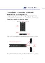
Motor & Drive 2.Photoelectric Transmitting Module and Photoelectric Receiving Module 2.1Installation Requirements for Photoelectric Transmitting Module and Photoelectric Receiving Module Figure 2-1 Top View of Installation for Transmitting Module and Driver (Receiver on the Side) Figure 2-2 Side View of Installation for Transmitting Module and Driver (Receiver on the Side)
Open the catalog to page 5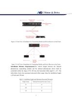
Carnage Travel Infrared Photoelectric Infrared Photoelectnc Module Infrared Photoelectnc Transmitter Module L odule offset direction Figure 2-4 Left View of Installation for Transmitting Module and Driver (Receiver on the Front) Installation Distance Requirements:The vertical height between the infrared photoelectric transmitting module and the infrared photoelectric driver shall be controlled within the range of 50-150 mm; the horizontal offset angle 9 < 18°. The table below shows the maximum horizontal offset range when the installation height is 50 mm and 150 mm. Table 2-1 Installation Height...
Open the catalog to page 6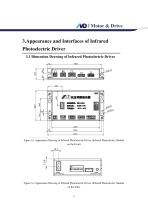
Motor & Drive 3.Appearance and Interfaces of Infrared Photoelectric Driver 3.1 Dimension Drawing of Infrared Photoelectric Driver Figure 3-1 Appearance Drawing of Infrared Photoelectric Driver (Infrared Photoelectric Module on the Front) Figure 3-2 Appearance Drawing of Infrared Photoelectric Driver (Infrared Photoelectric Module on the Side) 5
Open the catalog to page 7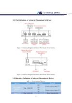
Motor & Drive 3.2 Pin Definition of Infrared Photoelectric Driver Figure 3-3 Schematic Diagram 1 of Infrared Photoelectric Driver Interface Figure 3-4 Schematic Diagram 2 of Infrared Photoelectric Driver Interface 3.2.1Interface Definition of Infrared Photoelectric Driver Table 3-1 Driver Interface Definition Interface Power Input Interface Remarks Connect to power input 48V+ Connect to power input 48VMotor outgoing cabl
Open the catalog to page 8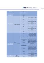
Motor & Drive Interface Motor Thermal Protection PTC Motor Encoder Interface Encoder differential signal FA+ Encoder differential signal FA- Encoder differential signal FB+ Encoder differential signal FB- Encoder differential signal FC+ Encoder differential signal FC- IO port power supply positive pole (internal) IO port power supply negative pole (internal) DIN1(Start/Stop) DIN2(Forward/Re verse) Motor Operation Control Interface Encoder signal power supply To improve anti-interference performance, COM1 is not connected to the internal circuit GND. Please refer to the wiring diagram below (NPN/PNP)...
Open the catalog to page 9All M&D (Motor and Drive) catalogs and technical brochures
 48V Servo Drive V1.0_EN
16 Pages
 F Series of ECI Motor
23 Pages
 T Series of ECI Motor
28 Pages
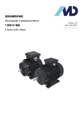 T Series of EC Motor
17 Pages
- Electromotor
- Synchronous motor
- Electromotor for industrial applications
- EC motor
- High-efficiency electromotor
- IP55 motor
- Permanent magnet motor
- Pump motor
- Robotic motor
- Conveyor motor
- IEC motor
- Blower motor
- Fan motor
- Linear motor
- Variable-speed motor
- Machine tool motor
- Compressor motor
- Motor driver
- Energy-saving motor
- High-precision motor