
- Catalogs
- M&D (Motor and Drive)
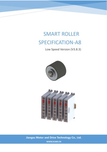
- SMART ROLLER CATALOGUE

SMART ROLLER CATALOGUE
SMART ROLLER CATALOGUE
This section outlines the revision history of the Smart Roller specification, detailing updates from the primary edition in 2018 to the latest in 2020, including changes in driver editions, protocol additions, and speed range adjustments.
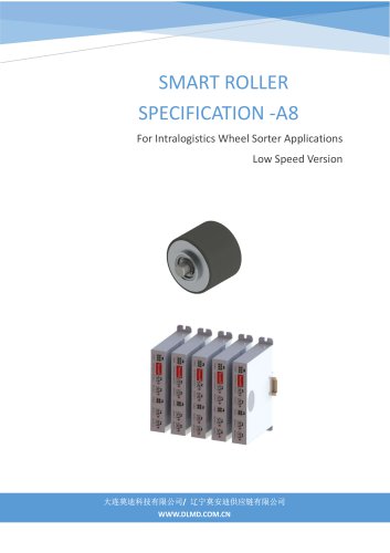
The Smart Roller features a permanent magnetic brushless motor without hall sensors, with an outer rotor and a roller diameter of 70mm. It operates at a rated voltage of 48V DC and a power of 50W, with a speed range of 150-850 rpm depending on the control mode.
The driver is a sensor-less BLDC type, supporting RS485 or IO control modes. It can operate in temperatures from -25°C to 60°C and humidity below 85%. The driver can control up to four roller motors synchronously.
Details the control signal ports and their configurations, emphasizing the priority of IO control over RS485 communication.
Explains the dip switch settings for both IO and RS485 modes, including speed and direction settings.
Defines the motor and power supply terminal connections, highlighting the importance of correct polarity to avoid damage.
Describes the LED status indicators for various operational states and fault conditions.
Outlines the RS485 communication protocol, including parameters for frame commands and responses.
Each motor undergoes rigorous testing for insulation performance and motor functionality before dispatch.
The product comes with a twelve-month warranty, excluding damages from improper installation or use.
Details the packaging and transportation methods, with rollers packed in dedicated cartons and drivers in cartons, transported as per contract agreements.
Catalog excerpts
SMART ROLLER SPECIFICATION -A8 For Intralogistics Wheel Sorter Applications Low Speed Version
Open the catalog to page 1
Smart Roller 电动滚筒 Primary edition Correct motor name Update terminal screw thread spec Modify dip switch for speed setting Increase speed range Increase to 8 speeds at IO control mode Redefined speed range of 200-775rpm at IO control mode Add phase open fault detecting function Add parameter setting frame for setting and saving up to 16speeds Add three levels of high and medium and Low speeds
Open the catalog to page 2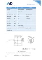
1. Roller Motor Specifications PARAMETER The roller surface is stuck with blue gum made of polyurethane in thickness 2mm.
Open the catalog to page 3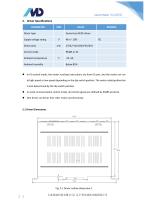
2. Driver Specifications PARAMETER • In IO control mode, the motor run/stop instructions are from IO port, and the motor can run at high speed or low speed depending on the dip switch position. The motor rotating direction is also determined by the dip switch position. • In serial communication control mode, all control signals are defined by RS485 protocol. • One driver can driver four roller motor synchronously.
Open the catalog to page 4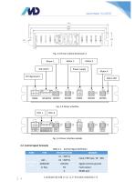
Smart Roller 电动滚筒 Fig. 2-2 Driver outline dimension-2 Motor 2 Power supply Ctrl Signal port Fig. 3-4 Driver interface details 2.2. Control Signal Termianls Table 2-1 Control Signal Definition PORT Ctrl Signal Port REMARK Input, PNP type, 18~48V Signal common ground Fault output
Open the catalog to page 5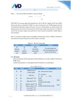
Note 1 : The circuit of INPT1 and INPT2 is shown as below: INPT1/INPT2 can receive signal with potential from 18V to 48V DC, typically DC24V and DC48V. Because the driver is powered by DC48V, it is more convenient to use a DC48V signal by directly connecting the 48V power supply to this port. If you use a DC24V signal, you should connect the signal ground to the common terminal port or the DC power supply source ground. It is better to connect the DC power supply source ground for noise immunity consideration. DC48V signal is recommended. Note 2: IO control has higher priority over RS485 communication...
Open the catalog to page 6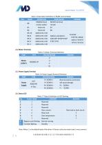
Table 2-4 Dip Switch Definition in RS485 Control Mode Note: Motor 1 is the default load of the driver. If there is only one motor load, it must connect
Open the catalog to page 7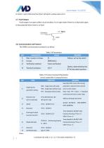
to motor 1 port otherwise the driver will alarm a phase open error. Fault output is an open collect circuit as below. It is in open state if there is no fault and it goes to low potential when there is an fault 2.8. Communication and Protocol The RS485 communication protocol is as below
Open the catalog to page 8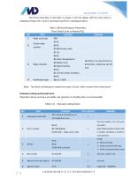
Smart Roller 电动滚筒 The frame head byte or start byte is unique, it will not appear with the same value in subsequent bytes. B7=1 only in start byte, but B7=0 in subsequent bytes. Table 2-10Frame Response Parameters (From Slave/Carrier to Master/PLC) NO Reply start byte Carrier code number Reply contents Verification byte Set bit to 1 in case of error or protection, otherwise set bit to 0. Note:The driver will attempt to restart the motor in 10 sec. after recovery from a fault event. Parameter setting write/read frame (Operation during running is accessible, but operation in standby state is recommended)...
Open the catalog to page 9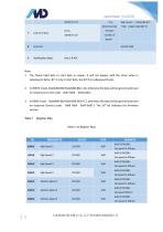
1. The frame head byte or start byte is unique, it will not appear with the same value in subsequent bytes. B7=1 only in start byte, but B7=0 in subsequent bytes. 2. In WRITE mode, Byte4(B0-B6)+Byte5(B0-B6)<=16, otherwise the data will be ignored and have no response (Correct code: 0x07 0x09 0x04 0x0C) 3. In READ mode, Byte4(B0-B6)+Byte5(B0-B6)<=17, otherwise the data will be ignored and have no response (Correct code: 0x08 0x09 0x04 0x0D ). The 16th bit indicates the firmware
Open the catalog to page 10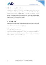
Smart Roller 电动滚筒 3. Quality Control and Surveillance Every set of motor dispatched from factory has a tracking inspection table, which can be traced back to the original size of each part. The insulation performance test includes winding voltage, resistance and turn-to-turn test. Back EMF method is used for motor performance test. All motors must pass the test before being dispatched. All drivers must pass the logic verification and the actual load test and aging test as well before delivery. 4.Warranty Period The warranty period is twelve months. Any damage due to inadequate installation or...
Open the catalog to page 12All M&D (Motor and Drive) catalogs and technical brochures
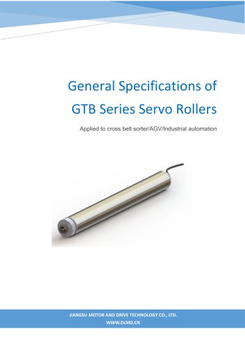 GTB Series Servo Rollers
15 Pages
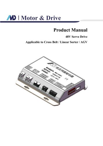 48V Servo Drive V1.0_EN
16 Pages
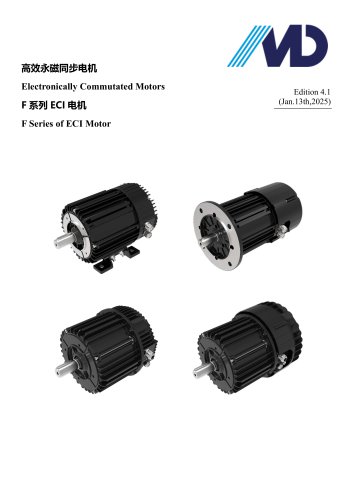 F Series of ECI Motor
23 Pages
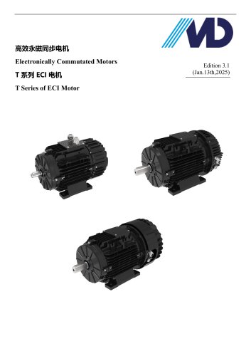 T Series of ECI Motor
28 Pages
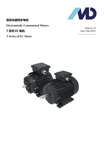 T Series of EC Motor
17 Pages
Archived catalogs
- Electromotor
- Synchronous motor
- Electromotor for industrial applications
- IP55 motor
- High-efficiency electromotor
- Pump motor
- Permanent magnet motor
- Robotic motor
- Conveyor motor
- IEC motor
- Fan motor
- Blower motor
- Machine tool motor
- Linear motor
- Variable-speed motor
- Motor driver
- High-precision motor
- Compressor motor
- Energy-saving motor