- Catalogs
- M&D (Motor and Drive)
- MDK-370+linear motor+V1.10(Linear Synchronous Motor & Drive)
MDK-370+linear motor+V1.10(Linear Synchronous Motor & Drive)
1 /114Pages

MDK-370+linear motor+V1.10(Linear Synchronous Motor & Drive)
1 /114Pages
Catalog excerpts
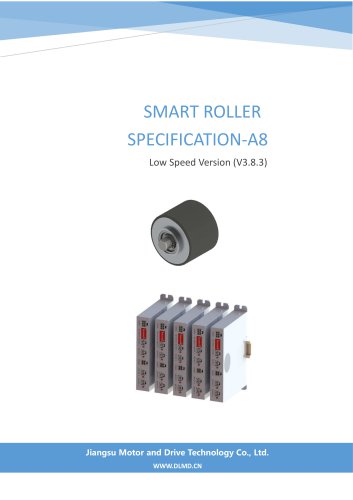
MDK-370 linear motor variable frequency drive manual
Open the catalog to page 1
MDK-370 linear motor variable frequency drive perface MDK-370 linear motor variable frequency drive perface Contact Information: Jiangsu Motor and Drive Technology Co., Ltd. No. 51 Weihai Road, Taicang, Suzhou City, Jiangsu Province, China 0512-53980061 www.dlmd.cn [email protected]
Open the catalog to page 2
MDK-370 linear motor variable frequency drive preface Thank you for purchasing the high-performance vector control variable frequency drive product. This user manual explains how to use this product correctly. Before use (installation, wiring, operation, maintenance, inspection, etc.), please be sure to read this user manual. matters needing attention Please make sure to confirm the integrity of the product casing and all safety covers during use, and operate according to the instructions in the user manual.
Open the catalog to page 3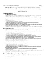
MDK-370 linear motor variable frequency drive perface Excellent Performance 1. Excellent driving performance • Truly achieved vector decoupling control of AC motors, while ensuring effective control of output current and DC bus voltage, achieving stable and trip free operation of the motor; • Adopting a closed-loop vector control mode with speed sensors to achieve precise control of motor speed, torque, and position. • Excellent current and voltage control technology; • Super strong load capacity, stable and trip free operation of the variable frequency drive under any acceleration and deceleration...
Open the catalog to page 4
MDK-370 linear motor variable frequency drive perface • Can provide PLC module expansion to achieve customized development and services for specific industry product applications
Open the catalog to page 5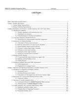
MDK370 Variable Frequency Drive catalogue
Open the catalog to page 6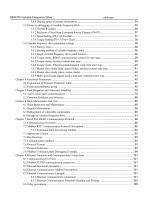
MDK370 Variable Frequency Drive catalogue
Open the catalog to page 7
MDK370 Variable Frequency Drive
Open the catalog to page 8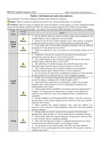
MDK370 Variable Frequency Drive Safety information and precautions Safety definition: The safety markings mentioned in this manual are as follows: anger: Failure to operate as required may result in fire, serious personal injury, or even death. ^^Attention: Failure to operate as required may result in moderate or minor injuries, as well as equipment damage. Please read this chapter carefully and follow the safety precautions required in this chapter when installing, debugging, and repairing this product. Any harm or loss caused by illegal operations is not related to our company.
Open the catalog to page 9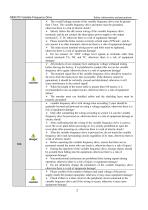
MDK370 Variable Frequency Drive Safety information and precautions
Open the catalog to page 10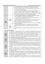
MDK370 Variable Frequency Drive Safety information and precautions M Other precautions Input
Open the catalog to page 11
MDK370 Variable Frequency Drive Safety information and precautions
Open the catalog to page 12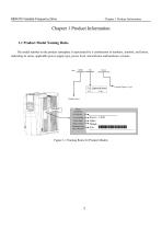
MDK370 Variable Frequency Drive Chapter 1 Product Information Chapter 1 Product Information 1.1 Product Model Naming Rules The model number on the product nameplate is represented by a combination of numbers, symbols, and letters, indicating its series, applicable power supply type, power level, and software and hardware versions. Figure 1-1 Naming Rules for Product Models
Open the catalog to page 13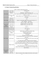
MDK370 Variable Frequency Drive Chapter 1 Product Information Table 1-1 Product Technical Specifications
Open the catalog to page 14
MDK370 Variable Frequency Drive Chapter 1 Product Information
Open the catalog to page 15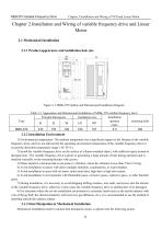
MDK370 Variable Frequency Drive Chapter 2 Installation and Wiring of VFD and Linear Motor Figure 2-1 MDK-370 Outline and Dimensional Installation Diagram Table 2-1 Appearance and Dimensional Installation of MDK-370 variable frequency drive 1) Environmental temperature: The ambient temperature has a significant impact on the lifespan of the variable frequency drive, and it is not allowed for the operating environment temperature of the variable frequency drive to exceed the allowable temperature range (-10~50 °C). 2) Install the variable frequency drive on the surface of a flame-retardant object,...
Open the catalog to page 16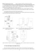
MDK370 Variable Frequency Drive Chapter 2 Installation and Wiring of VFD and Linear Motor 1) The high-performance vector control type variable frequency drive is a wall mounted variable frequency drive and should be installed vertically to facilitate air circulation and heat dissipation. Adequate space should be left around the variable frequency drive as shown in Figure 2-1, and the position of the ventilation fan in the installation environment of the variable frequency drive is shown in Figure 2-2. 2) For the installation of multiple wall mounted variable frequency drive, as shown in Figures...
Open the catalog to page 17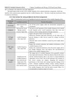
MDK370 Variable Frequency Drive Chapter 2 Installation and Wiring of VFD and Linear Motor drive or damage to the capacitors and surge suppressors. The input/output (main circuit) of the variable frequency drive contains harmonic components, which may interfere with communication equipment near the variable frequency drive. Therefore, install anti-interference filters to minimize interference. Table 2-2 Instructions for the use of peripheral electrical components of the variable frequency drive
Open the catalog to page 18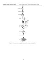
MDK370 Variable Frequency Drive Chapter 2 Installation and Wiring of VFD and Linear Motor Figure 2-6 Connection between variable frequency drive and peripheral devices
Open the catalog to page 19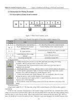
MDK370 Variable Frequency Drive Chapter 2 Installation and Wiring of VFD and Linear Motor Table 2-3 Main Circuit Terminal Descri Wiring precautions: Wiring precautions: a) Input power supply R, S, T: The input side wiring of the variable frequency drive has no phase sequence requirements. b) DC bus+and - terminals: Note that there is still residual voltage on the DC bus+and - terminals after a power outage. It is necessary to wait for the REV light to turn off and confirm that it is less than 36V before making contact, otherwise there is a risk of electric shock. When using external brake components...
Open the catalog to page 20
MDK370 Variable Frequency Drive Chapter 2 Installation and Wiring of VFD and Linear Motor or even fire. The wiring length of the braking unit should not exceed 10m, and twisted pair or tight double line parallel wiring should be used. Do not directly connect the braking resistor to the DC bus, as it may cause damage to the variable frequency drive or even fire. c) The connection terminals PB and P+of the braking resistor should be selected according to the recommended values. The wiring distance should be less than 5m, otherwise it may cause damage to the variable frequency drive. d) variable...
Open the catalog to page 21All M&D (Motor and Drive) catalogs and technical brochures
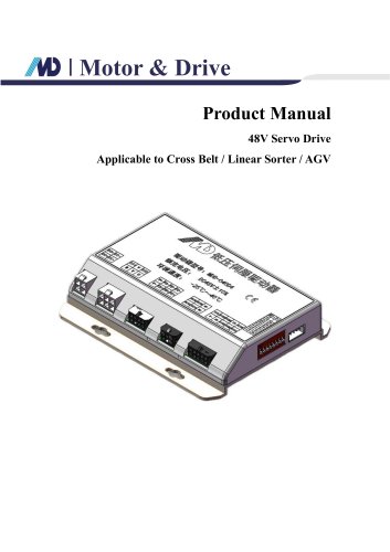 48V Servo Drive V1.0_EN
16 Pages
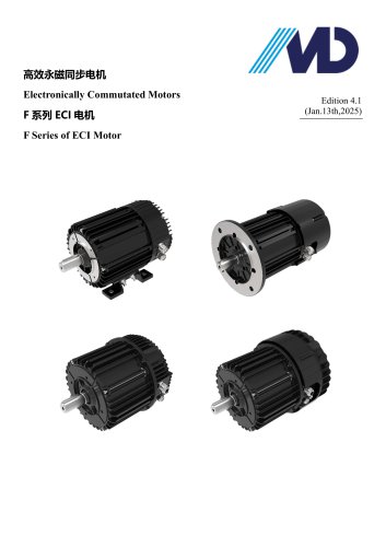 F Series of ECI Motor
23 Pages
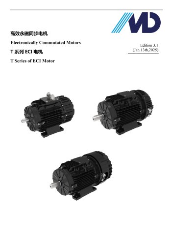 T Series of ECI Motor
28 Pages
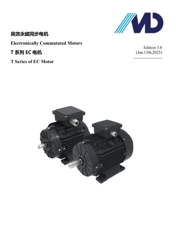 T Series of EC Motor
17 Pages
- Electromotor
- Synchronous motor
- Electromotor for industrial applications
- EC motor
- High-efficiency electromotor
- IP55 motor
- Permanent magnet motor
- Pump motor
- Robotic motor
- Conveyor motor
- IEC motor
- Blower motor
- Fan motor
- Variable-speed motor
- Machine tool motor
- Compressor motor
- Motor driver
- Energy-saving motor
- High-precision motor