- Catalogs
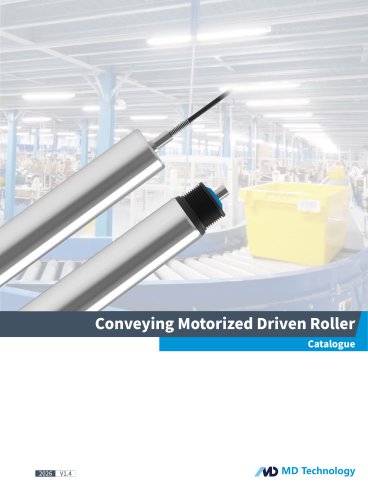
- M&D (Motor and Drive)
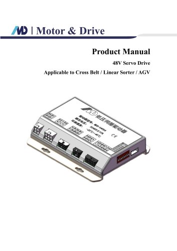
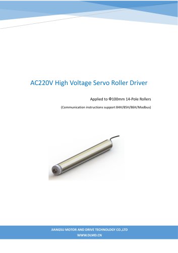
- MDI Servo Drive Product Manual V1.5(DMD Roller Drive)
MDI Servo Drive Product Manual V1.5(DMD Roller Drive)
1 /20Pages
MDI Servo Drive Product Manual V1.5(DMD Roller Drive)
1 /20Pages
Catalog excerpts

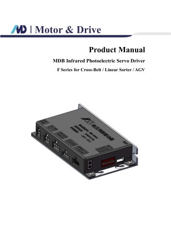
Product Manual MDI Servo Drive
Open the catalog to page 1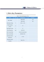
Table 1-1 Drive Key Parameters Table
Open the catalog to page 3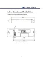
Figure 2-1 Drive External Dimensions
Open the catalog to page 4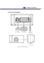
Motor & Drive 2.2 Drive Port Definition Figure 2-2 Drive Port Definition
Open the catalog to page 5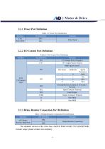
2.2.1 Power Port Definition Table 2-1 Power Port Definition
Open the catalog to page 6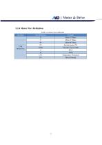
Table 2-4 Motor Port Definition
Open the catalog to page 7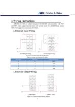
Motor & Drive3.Wiring Instructions DI1/DI2/DI3/DO are isolated designed. DI1/DI2/DI3 are compatible with PNP and NPN inputs, supporting maximum 24V system input. DO and COM can output NPN/PNP, supporting maximum 24V/50mA. A. PNP Input Wiring B. NPN Input Wiring Figure 3-1 Isolated Input Wiring Diagram Table 3-1 Multi-speed Definition Table
Open the catalog to page 8
Motor & Drive Under normal status after power-on, the drive's DO and COM are in conducting state; in case of fault, they are in disconnected state.
Open the catalog to page 9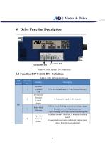
Figure 4-1 Drive Function DIP Switch Area Table 4-1 DS1 DIP Switch Definition
Open the catalog to page 10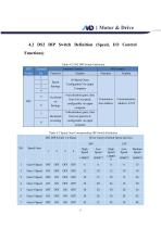
Table 4-2 DS2 DIP Switch Definition
Open the catalog to page 11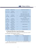
Note: When viewed from the motor lead-out side, counterclockwise rotation is regarded as forward (normal) rotation.
Open the catalog to page 13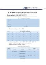
Table 5-1 Communication Description
Open the catalog to page 14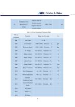
Motor & Drive Positive value for Speed Gear 15 Setting forward rotation, negative value for reverse rotation Table 5-4 Drive Monitoring Parameters Table Fault Code Actual Speed Reference Speed Output Current Output Voltage Output Power Output Torque Torque Command Drive Temperature Motor Temperature Encoder Mechanical Angle Encoder
Open the catalog to page 18
Latest Fault
Open the catalog to page 19All M&D (Motor and Drive) catalogs and technical brochures
 48V Servo Drive V1.0_EN
16 Pages
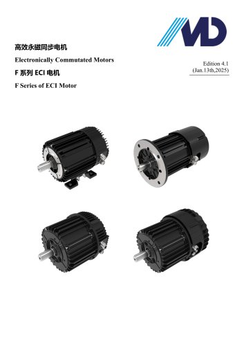 F Series of ECI Motor
23 Pages
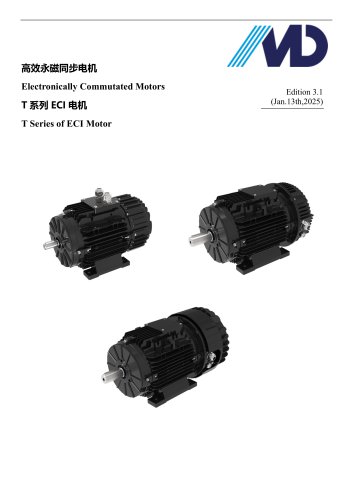 T Series of ECI Motor
28 Pages
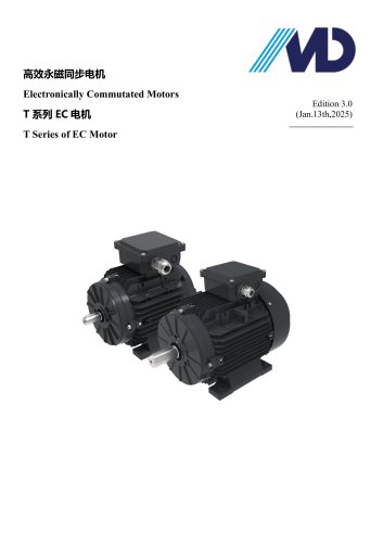 T Series of EC Motor
17 Pages
- Electromotor
- Synchronous motor
- Electromotor for industrial applications
- EC motor
- High-efficiency electromotor
- IP55 motor
- Permanent magnet motor
- Pump motor
- Robotic motor
- Conveyor motor
- IEC motor
- Blower motor
- Fan motor
- Linear motor
- Variable-speed motor
- Machine tool motor
- Compressor motor
- Motor driver
- Energy-saving motor
- High-precision motor