
- Catalogs
- M&D (Motor and Drive)
- GTB Series Servo Rollers

GTB Series Servo Rollers
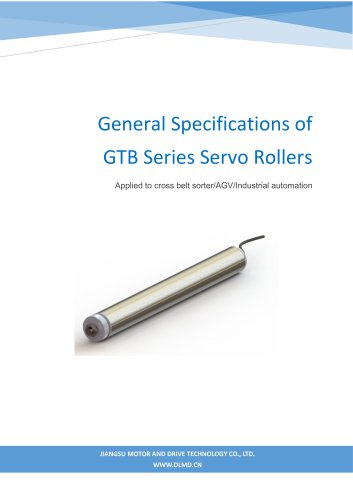
GTB Series Servo Rollers
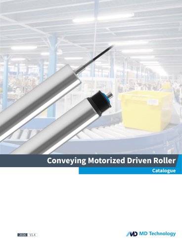
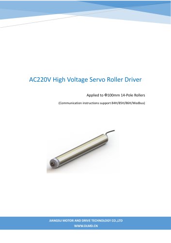
The GTB Series Servo Rollers are equipped with a permanent magnetic brushless DC motor featuring an outer rotor. They come in diameters of 50 mm and 67 mm, suitable for sorting packages weighing up to 15 kg and 25 kg, respectively. The rated voltage is 48 V DC with a power output of 200 W and a maximum current of 20 A. The velocity range is 100 to 762 rpm, with a linear speed of 1 to 1.2 m/s. The working duty is S2 with a maximum of 25% intermittent work, and the insulation class is F.
Roller Driver Specifications
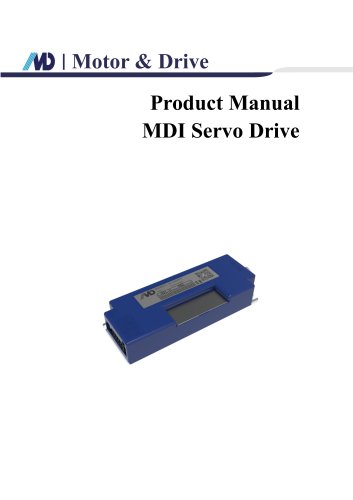
The driver model MDB-040D4R01A PS48D56L operates at a supply voltage of 48 V DC. It supports RS485 communication at 38400 bps and functions within an ambient temperature range of -25 to 60°C and humidity below 85%.
Dimensions and Port Definitions
The driver dimensions are 123.7 x 104.4 x 28 mm. It includes ports for motor phase, thermal protection, power supply, communication, encoder, and control signals. The wiring supports both NPN and PNP configurations.
Communication Protocol
The driver communicates with PLCs via RS485 using a specific protocol. It supports up to 31 carriers with a format of 38400,N,8,1. The protocol includes trigger commands and parameter frames for operation.
Debug and Test
Pre-operation checks include ensuring correct wiring and using a suitable power supply. Recommended parameters for unloading and loading operations are provided, with suggestions for optimizing performance.
Quality Control and Inspection
All motors undergo rigorous testing, including insulation performance and motor performance tests. Drives are verified through logic and operational tests before delivery.
Warranty and Packaging
The warranty period is one year, with maintenance fees applicable for abnormal use. Packaging involves cartons and wooden boxes, with transportation determined by contract requirements.
Edition
Product upgrades are available, and users are advised to confirm software and hardware versions with the company.
Catalog excerpts
General Specifications of GTB Series Servo Rollers Applied to cross belt sorter/AGV/Industrial automation JIANGSU MOTOR AND DRIVE TECHNOLOGY CO., LTD. WWW.DLMD.CN
Open the catalog to page 1
General Specifications of GTB Series Servo Rollers Revision history Version JIANGSU MOTOR AND DRIVE TECHNOLOGY CO., LTD.
Open the catalog to page 2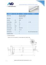
General Specifications of GTB Series Servo Rollers Diameter 50 mm roller applied for sorting packages with weight 0-15kg. JIANGSU MOTOR AND DRIVE TECHNOLOGY CO., LTD.
Open the catalog to page 3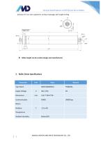
General Specifications of GTB Series Servo Rollers Diameter 67 mm roller applied for sorting of packages with weight 0-25kg. Roller length can be custom-design and manufactured 2. Roller Driver Specifications Type Name Supply Voltage Dimensions Means Ambient Temperature Ambient Humidity JIANGSU MOTOR AND DRIVE TECHNOLOGY CO., LTD
Open the catalog to page 4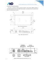
General Specifications of GTB Series Servo Rollers 2.1 Dimensions and Port Definition The driver is powered by 48V DC supply and delivers output power 200Watt working in intermittent mode with duty 25%, RS485 communication and terminal I/Os are used for motor speed and rotating direction control. Fig.2-2 Side view dimensions JIANGSU MOTOR AND DRIVE TECHNOLOGY CO., LTD.
Open the catalog to page 5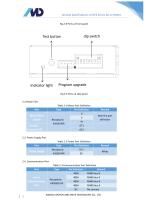
General Specifications of GTB Series Servo Rollers Fig.2-3 Ports at front panel Indicator light Program upgrade 2.2.Motor Port Table 2-1 Motor Port Definition JIANGSU MOTOR AND DRIVE TECHNOLOGY CO., LTD.
Open the catalog to page 6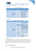
General Specifications of GTB Series Servo Rollers Table 2-4 Encoder Port Definition 2.6. Control Signal Port In order to achieve better operation performance, the drive are compatible with internal and external electrical interface, such as NPN and PNP circuit. If the external needs PLC long-term control operation, the external electrical wiring method can be selected; if only internal test in the factory, the internal electrical wiring method can be selected. Detailed descriptions are as below. JIANGSU MOTOR AND DRIVE TECHNOLOGY CO., LTD.
Open the catalog to page 7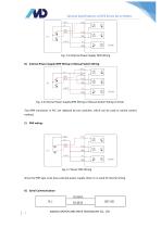
General Specifications of GTB Series Servo Rollers Fig. 2-5 External Power Supply NPN Wiring B) Internal Power Supply NPN Wiring or Manual Switch Wiring Fig. 2-6 Internal Power Supply NPN Wiring or Manual Switch Wiring in Driver Two NPN transistors in PLC are replaced by two switches, which can be used as switch control method. C) PNP wiring: Fig. 2-7 Driver PNP Wiring Since the PNP type must have external power supply, there is no need of internal wiring. JIANGSU MOTOR AND DRIVE TECHNOLOGY CO., LTD.
Open the catalog to page 8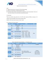
General Specifications of GTB Series Servo Rollers Fig.2-8 Communication with PLC (1) Highly recommend star connection for field wiring topology; (2) Please use twisted pair or shielded twisted pair lines; (3) Terminal resistors at both ends of the lines are optional for serial communication. Use one or two resistors based on the actual field communication situation. Please pay attention that position bits of the DIP switch represent different meanings in IO operation mode and RS485 communication operation mode. ON/OFF of DIP switch means function of valid / invalid. JIANGSU MOTOR AND DRIVE TECHNOLOGY...
Open the catalog to page 9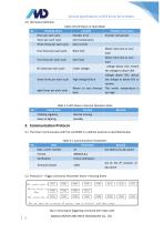
General Specifications of GTB Series Servo Rollers 2.9. LED Status Definition Table 2-8 LED Status in Fault Mode No Flashing times Possible root cause Once per each cycle Encoder error Twice per each cycle Over temperature Three times per each cycle Over current Four times per each cycle Rotor lock Motor rotor lock or over load Five times per each cycle Over load Motor rotor lock or over load Six times per each cycle Under voltage voltage below 25V, restore the voltage to above 30V Encoder wiring fault Seven times per each cycle High voltage failure Voltage above 70V, reduce the voltage to below...
Open the catalog to page 10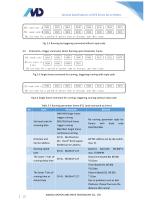
General Specifications of GTB Series Servo Rollers Fig. 3.2 Running by triggering command without reply code 3.3. Protocol B—Trigger command, Direct Running upon Parameter Frame Fig.3.3 Single frame command for running, triggering running with reply code Fig.3.4 Single frame command for running, triggering running without reply code Table 3-2 Running parameter frame (PLC send command to driver) No Set head code for receiving data 84H/94H:Single frame trigger running 85H/95H:Dual frame trigger running 86H/96H: Single frame continuous running No running parameter reply for frames with head code...
Open the catalog to page 11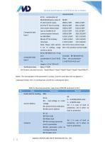
General Specifications of GTB Series Servo Rollers measurement. Composite data byte 1 B6,B5,B4,B3 gives value of PI, B2=Control mode, B1=The 8th bit of running time and/or distant byte (use as Enable bit of communication timeout for 86H/96H) B0=the 8th bit of delay time byte Note: Please refer section B2==0 for time control mode 3 for PI setting, range B2==1 for position control mode 10/16 to 16/16. composite data byte 2 Example: B6~B0=0X3F=63 Then the acceleration= 1.5+63*0.05=4.65 m/s2 range is 1.5 to 7.85 m/s2 Verification byte Byte 2-7 XOR Notes: The starting byte of the parameter is unique,...
Open the catalog to page 12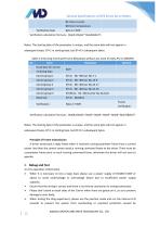
General Specifications of GTB Series Servo Rollers Verification calculation formula: Byte4=(Byte2A Byte3)&0x7F; Notes: The starting byte of the parameter is unique, and the same byte will not appear in subsequent bytes. B7=1 in starting byte, but B7=0 in subsequent bytes. Table 3-4 Running Command Frame (Broadcast without any need of reply, PLC to DRIVER) Notes: The starting byte of the parameter is unique, and the same byte will not appear in subsequent bytes. B7=1 in starting byte, but B7=0 in subsequent bytes. Principle of Frame transmission A driver sends back a reply frame when it received...
Open the catalog to page 13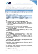
General Specifications of GTB Series Servo Rollers continuous overload. Set the 1st bit of the dip switch to ON position to enter communication control mode, then you can control a Carrier to run via RS485 serial communication control. The below table data are in hex format. (1) After sending 95H, the running frame can be sent directly without waiting. (2) After sending 85H, the driver will wait for 2ms and then send back code, so it is recommended to send parameter frame 85H and then send running frame after 10ms to prevent bus conflict. 4.2. Recommended Parameters for Unloading and/or Loading...
Open the catalog to page 14All M&D (Motor and Drive) catalogs and technical brochures
 SMART ROLLER CATALOGUE
12 Pages
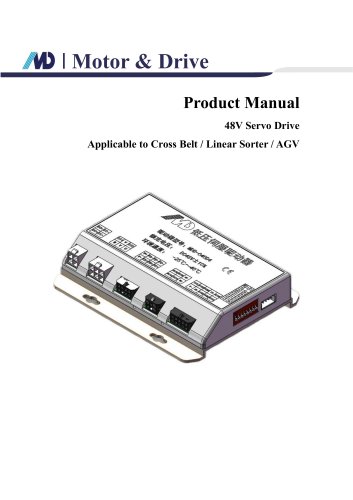 48V Servo Drive V1.0_EN
16 Pages
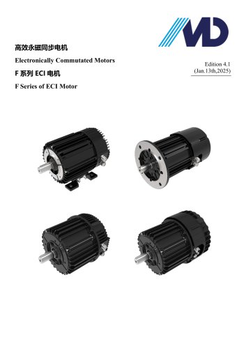 F Series of ECI Motor
23 Pages
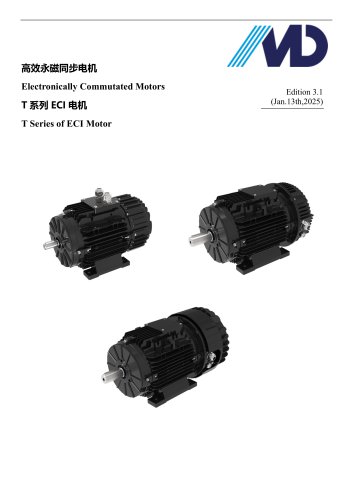 T Series of ECI Motor
28 Pages
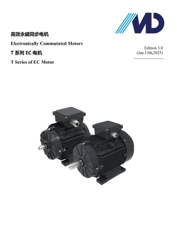 T Series of EC Motor
17 Pages
Archived catalogs
- Electromotor
- Synchronous motor
- EC motor
- Electromotor for industrial applications
- IP55 motor
- High-efficiency electromotor
- Pump motor
- Permanent magnet motor
- Robotic motor
- Conveyor motor
- IEC motor
- Fan motor
- Blower motor
- Machine tool motor
- Linear motor
- Variable-speed motor
- Motor driver
- High-precision motor
- Compressor motor
- Energy-saving motor