- Catalogs
- M&D (Motor and Drive)
- 48V Servo Drive V1.0_EN
48V Servo Drive V1.0_EN
1 /16Pages
48V Servo Drive V1.0_EN
1 /16Pages
Catalog excerpts
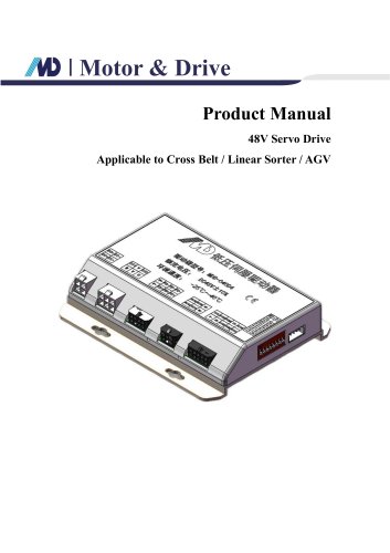
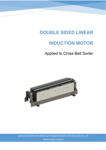
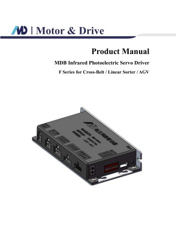
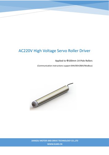
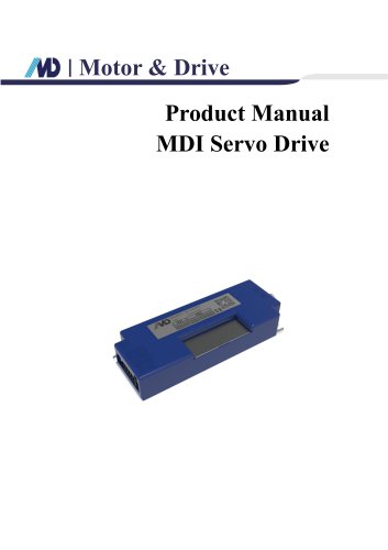
Motor & Drive Product Manual 48V Servo Drive Applicable to Cross Belt / Linear Sorter / AGV
Open the catalog to page 1
5.2.2 Communication Protocol B Triggered Operation, Direct Operation via Parameter Frame... 13 Historical Versions
Open the catalog to page 2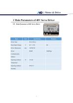
1.1 Main Parameters of 48V Servo Driver Item
Open the catalog to page 3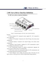
Motor & Drive 2 48V Servo Driver Interface Definition 2.1 48V Servo Driver Interface Definition Figure 2-1 Schematic Diagram of 48V Servo Driver Interface Definition Remarks: ① Power Interface: DC+ connected to power supply 48V+, DC- connected to power supply 48V-; ② Motor UVW Interface: Connected to the white 6P plug of the electric drum outgoing line; ③ Encoder Interface: Connected to the white 8P plug of the electric drum outgoing line; ④ Operation Control Interface: Adopting IO or 485 communication control, black 10P plug (non-photoelectric control); ⑤ 485 Communication Interface: In addition...
Open the catalog to page 4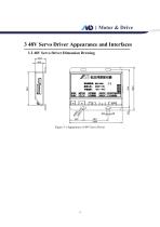
Motor & Drive 3 48V Servo Driver Appearance and Interfaces 3.1 48V Servo Driver Dimension Drawing Figure 3-1 Appearance of 48V Servo Driver
Open the catalog to page 5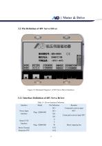
Motor & Drive 3.2 Pin Definition of 48V Servo Driver Figure 3-2 Schematic Diagram 1 of 48V Servo Driver Interfaces 3.2.1 Interface Definition of 48V Servo Driver Table 3-1 Driver Interface Definition Interface Power Input Interface Connected to power input 48V+ Connected to power input 48V- Motor Thermal Protection PTC
Open the catalog to page 6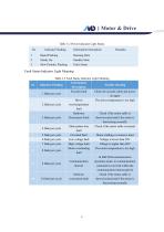
Table 3-2 Power Indicator Light Status
Open the catalog to page 8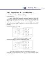
Motor & Drive 4 48V Servo Driver IO Control Settings 4.1 48V Servo Driver IO Control Wiring Wiring Instructions: To ensure optimal product performance, the product supports both internal and external power supply modes when operating in IO mode, and is also compatible with NPN and PNP wiring. For long-term controlled operation with external devices such as PLC, the external power supply wiring mode is recommended; for in-plant testing only, the internal power supply wiring mode can be selected. Detailed instructions are as follows. External Power Supply NPN Wiring: Figure 4-1 Driver External...
Open the catalog to page 9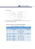
I Motor & Drive PNP Wiring Method: 4.2 48V Servo Driver IO Control DIP Switch Definition Table 4-4 DIP Switch Definition - IO Operation Mode
Open the catalog to page 10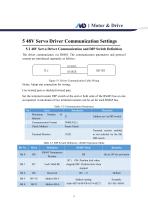
The driver communicates via RS485. The communication parameters and protocol content are introduced separately as follows: Use twisted pair or shielded twisted pair; Set the terminal resistor DIP switch at the end or both ends of the RS485 bus on site as required. A maximum of two terminal resistors can be set for each RS485 bus. Table 5-2 Communication Parameters
Open the catalog to page 11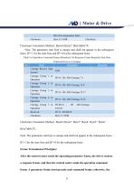
Note: The parameter start byte is unique and shall not appear in the subsequent bytes. B7=1 for the start byte and B7=0 for the subsequent bytes. Frame Transmission Principles: After the control center sends the operating parameter frame, the driver returns a response frame, and then the control center sends the operation command frame. A parameter frame must precede each command frame; otherwise, the
Open the catalog to page 14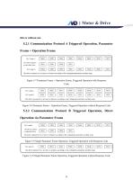
Motor & Drive driver will not act. 5.2.1 Communication Protocol A Triggered Operation, Parameter Frame + Operation Frame Figure 5-7 Parameter Frame + Operation Frame, Triggered Operation with Response Code Figure 5-8 Parameter Frame + Operation Frame, Triggered Operation without Response Code 5.2.2 Communication Protocol B Triggered Operation, Direct Operation via Parameter Frame Figure 5-9 Single Parameter Frame Operation, Triggered Operation with Response Code Figure 5-10 Single Parameter Frame Operation, Triggered Operation without Response Code
Open the catalog to page 15All M&D (Motor and Drive) catalogs and technical brochures
 F Series of ECI Motor
23 Pages
 T Series of ECI Motor
28 Pages
 T Series of EC Motor
17 Pages
- Electromotor
- Synchronous motor
- Electromotor for industrial applications
- EC motor
- High-efficiency electromotor
- IP55 motor
- Permanent magnet motor
- Pump motor
- Robotic motor
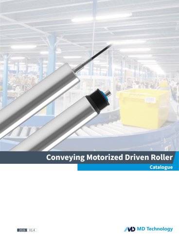
- Conveyor motor
- IEC motor
- Blower motor
- Fan motor
- Linear motor
- Variable-speed motor
- Machine tool motor
- Compressor motor
- Motor driver
- Energy-saving motor
- High-precision motor