Catalog excerpts

Instruction manual for rescue equipment Cutters and Combi Tools Blade forms: (Translation of the original instruction manual)
Open the catalog to page 1
4.4 Control of the operating movements 5.3 Coupling the quick-disconnect couplings 7. Cutting, spreading, pulling and squeezing 6.2 Operating the star grip 7.3 Spreading (combi tools only) 7.4 Pulling (combi tools only) 7.5 Squeezing (combi tools only) 8. Dismantling the equipment / deactivation following operation 8.1 Cutters / Combi tools 9.1 Cutters / Combi tools, overall
Open the catalog to page 2
12.3 Torque of the pivot bolt 12.5 Datasheets for the product performance 12.6 Recommended hydraulic fluid 12.7 Operating and storage temperature ranges
Open the catalog to page 3
We distinguish between various categories of safety notes. The table below gives you an overview of the assignment of symbols (pictograms) and key words to the specific hazard and possible consequences. Immediate danger Death or major injury Potentially dangerous situation Potential death or major injury Less dangerous situation Minor or slight injury Danger of damage to device / environment Damage to the equipment, damage to the environment, damage to surrounding materials Advice for application and other important / useful information and advice No injury / damage to persons / environment...
Open the catalog to page 4
LUKAS products are developed and manufactured in order to guarantee the best performance and quality when used properly. Operator safety is the most important aspect of the product design. Moreover, the operating instructions are intended to help the safe use of LUKAS products. The generally applicable, legal and other binding regulations pertaining to the prevention of accidents and protection of the environment apply and are to be implemented in addition to the operating instructions. The equipment may only be operated by persons with appropriate training in the safety aspects of such...
Open the catalog to page 5
Observe all safety and danger notes on the equipment and in the operating instructions. All safety and danger notes on the equipment are to be kept complete in a legible condition. Any mode of operation which impairs safety and/or stability of the equipment is forbidden! Comply with all specified dates or dates specified in the operating instructions pertaining to regular controls / inspections on the equipment. Safety devices may never be deactivated! The maximum permitted operating pressure noted on the equipment must not be exceeded. Before the equipment is switched on/started up, and...
Open the catalog to page 6
Always keep these operating instructions within reach where the equipment is used. Ensure the proper disposal of all removed parts, left-over oil and hydraulic fluid as well as packaging materials! The generally applicable, legal and other binding national and international regulations pertaining to the prevention of accidents and protection of the environment apply and are to be implemented in addition to the operating instructions. The equipment is to be used exclusively for the purpose stated in the operating instructions (see chapter “Proper Use”). Any other or further use is not...
Open the catalog to page 7
LUKAS “SC” combi tools and LUKAS “S” cutters are designed specifically for rescuing victims in traffic, rail or air accidents and for making rescues from buildings. They serve the purpose of freeing injured people in accidents e. g. by cutting doors, roof bars and hinges. By using the LUKAS combi tools, trapped persons can also be freed e. g. by spreading doors and / or by removing obstacles with the aid of a chainset. Basically, the combi tools can be used to cut, pull, spread, squeeze and lift. Basically, LUKAS cutters can only be used to cut objects. All objects which are to be worked on...
Open the catalog to page 8
LUKAS cutters and combi tools can also be used under water at a depth of up to 40m (131 ft). CAUTION! In this case, you must strictly observe any leaks in order to avoid threats to the environment. CAUTION! All objects which are to be worked on are to be secured using stable supports or substructures. WARNING / CAUTION! The following may not be cut / squeezed: - cables live - hardened parts such as springs, spring steels, steering columns and rollers - tubes / hoses under gas or liquid pressure, - compound materials (steel/concrete) - explosive bodies such as airbag cartouches NEVER operate...
Open the catalog to page 9
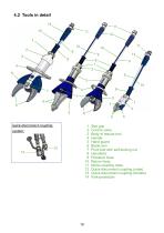
quick-disconnect coupling 1 Star grip 2 Control valve 3 Body of rescue tool 4 Handle 5 Hand guard 6 Blade arm 7 Pivot bolt with self-locking nut 8 Handhold 9 Pressure hose 10 Return hose 11 Mono-coupling male 12 Quick-disconnect coupling (male) 13 Quick-disconnect coupling (female) 14 Kink-protection
Open the catalog to page 10
quick-disconnect coupling 1 Star grip 2 Control valve 3 Body of rescue tool 4 Handle 5 Hand guard 6 Blade arm 7 Pivot bolt with self-locking nut 8 Handhold 9 Pressure hose 10 Return hose 11 Mono-coupling male 12 Quick-disconnect coupling (male) 13 Quick-disconnect coupling (female) 14 Kink-protection
Open the catalog to page 11
To enable comprehension of the function, a simplified hydraulic cylinder of the rescue equipment (A) + hand valve (B) are depicted here. cut / close / pulling / squeezing spreading / opening 4.4 Control of the operating movements The spreading arms movement is controlled via the star grip of the mounted valve. (see cover, item 1 and, below, figure 3). star grip A LUKAS motor pump or hand pump only may be used to drive the equipment. If the pump unit is a different make, you must make sure that it complies with LUKAS specifications, otherwise potential dangers may occur which are not the...
Open the catalog to page 12
5. Connecting the equipment 5.1 General information There are two short hoses on the side of the equipment: they are connected to the pump unit via two hoses. All hose assemblies are marked with a colour and have couplings to enable unmistakable connection. REMARK: The devices can be equipped with different coupling systems. They differ only by the article number and not by the designation. Of course the coupling systems can also be reequipped at a later time. WARNING / CAUTION! Before connecting the equipment you have to pay attention that all used components are suitable to the max...
Open the catalog to page 13All LUKAS Hydraulik GmbH catalogs and technical brochures
-
SP 777 E2
15 Pages
-
Catalog Industrial
51 Pages


