

CDM9

CDM9
This document is an operational guide for the CDM9 Conductivity Controller, including a three-year product guarantee against defects, with limitations on misuse and modifications. LTH Electronics Ltd may update the manual or instrument without notice.
The CDM9 complies with European EMC Directives and the European Low Voltage Directive, manufactured under ISO 9001:2000 standards.
The CDM9 is compatible with various LTH conductivity cells and offers measurement ranges of 0-19.99 µS/cm, 0-199.9 µS/cm, and 0-1999 µS/cm. It includes a volt-free changeover relay for dosing or bleeding applications, with factory calibration.
The CDM9 supports multiple cell types, operates at 190Hz, and offers a conductivity accuracy of 2% of reading ± 2 digits. It has a fixed temperature compensation slope of 2%/°C, powered by 110V or 230V AC, and housed in flame-retardant ABS plastic.
Instructions are provided for wall-mount, rail-mount, pipe-mount, and panel-mount versions. Recommended cables should be used to maintain EMC compliance, with diagrams for sensor wiring.
The CDM9 allows setting the operating range, display decimal point, process temperature, and temperature compensation. Relay setpoints can be adjusted via front panel switches.
Checklists are included for troubleshooting common issues with the CDM9, such as incorrect wiring or cell mounting.
Details on the product guarantee and service options are provided, emphasizing not dismantling the unit to maintain the guarantee.
Ensure no tension on cables within the instrument to prevent strain on connectors. Use recommended cables for extensions and ensure proper sealing to prevent RF interference. Disconnect mains power before making changes.
Ensure proper connection of the conductivity cell using specified terminals and cables. Relay contacts should be connected with a supply, load, and a 5 Amp fuse. Noise suppression measures include fitting arc suppressors and using earthed steel trunking for signal cables.
Follow systematic procedures for setting up the CDM9. Configure option switches carefully and refer to diagrams for accessing setup controls. Set operating ranges and display decimal points according to application needs.
Common issues include incorrect wiring or cell mounting. Check power supply voltage, connections, and ensure the cell is not clogged or damaged.
Apply recommended wiring practices to minimize interference. Use internal relays to switch external relays for heavy loads. Fit in-line mains filters if necessary.
Ensure a minimum isolation resistance of 50 MΩ between terminals E & C. Check for air traps in the cell installation and verify the integrity of the cell cable.
Ensure the cell is unobstructed and measures a representative sample. Ensure thorough mixing of solution additives and appropriate flow rates.
LTH Electronics Ltd guarantees products against faulty workmanship and materials for three years from dispatch. Goods under guarantee must be returned carriage paid for free repair.
Catalog excerpts
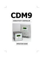
OPERATION GUIDE
Open the catalog to page 1
Preface Product guarantee This instrument has a guarantee against defects in materials and workmanship for a period of three years from the date of shipment. During this period LTH will, at its own discretion, either repair or replace products that prove to be defective. Limitation of guarantee The foregoing guarantee does not cover damage caused by accidental misuse, abuse, neglect, misapplication or modification. No guarantee of fitness for a particular purpose is offered. The user assumes the entire risk of using the product. Any liability of LTH is limited exclusively to the replacement of...
Open the catalog to page 2
Manufacturing Standards Electromagnetic compatibility This instrument has been designed to comply with the standards and regulations called up by the European EMC Directives. Safety This instrument has been designed to comply with the standards and regulations called up by the European Low Voltage Directive using BS EN 61010-1 : 1993 Quality This instrument has been manufactured under the following quality standard: ISO 9001:2000. Certificate No: FM 13843 Note: The standards referred to in the design and construction of LTH products are those prevailing at the time of product launch. As the standards...
Open the catalog to page 3
This page is intentionally blank
Open the catalog to page 5
1 Introduction The CDM9 can be used with a wide range of LTH conventional conductivity cells to measure and control a broad spectrum of solution conductivity. Two versions of the basic CDM9 are available. The Wall-mount version, and the Panel-mount version. Three measurement ranges can be selected using a combination of switch settings and cell constants (1.0 and 0.1). The ranges are: -♦ 0 - 19.99 pS/cm The CDM9 has an onboard volt-free changeover relay with an adjustable setpoint. It can be set to activate if the conductivity is above or below the setpoint. Therefore, the CDM9 can be used...
Open the catalog to page 6
Cell types which can be used with the CDM9 Cable length Operating frequency_ Ranges of measurement Conductivity accuracy Linearity Repeatability Ambient temperature Temperature variation Temp. compensation slope Temp. compensation point Temp. compensation base Display Control relay EMC : Immunity EMC :Emissions LVD : Safety standard Power supply Panel-mount housing Panel-mount weight Panel-mount environmental Panel-mount dimensions Wall-mount housing Wall-mount weight Wall-mount environmental Wall-mount dimensions Up to 25 metres. Cell : approx 190Hz, sinusoidal_ -20°C to +50°C for full specification....
Open the catalog to page 7
2 Installation This chapter describes how to install the wall-mount, rail-mount, pipe-mount and panelmount versions, and how to connect the unit to auxiliary equipment and a power source. Wall-mount version The wall-mount version is designed for fixing to a wall or other flat surface using the brackets provided. Mounting brackets and dimensions The brackets should be attached, either horizontally or vertically, to the back of the CDM9 using the four M4 pan head screws provided.
Open the catalog to page 8
Rail-mount and pipe-mount versions The rail- & pipe-mount brackets are designed for fixing the wall-mount version to a vertical or horizontal handrail or pipe, of 25 mm min. to 60 mm maximum outside diameter. The rail-mounting kit comprises two channels, two clamps and appropriate studs, nuts and washers, as shown in the exploded view below. To mount the rail-mount version proceed as follows: ♦ ♦ ♦ Attach the four studs to the channels using four pairs of nuts and washers as shown in the following diagram. The studding must not protrude beyond the nut on the flat side of each channel Attach the...
Open the catalog to page 9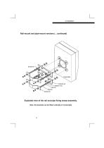
Rail-mount and pipe-mount versions (…continued) Exploded view of the rail and pipe fixing clamp assembly. Note: the brackets can be fitted vertically or horizontally
Open the catalog to page 10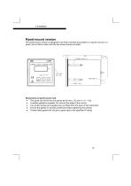
Panel-mount version The panel-mount version is designed to be flush mounted and sealed in a square cut-out in a panel, and is held in place with the two screw clamps provided. Dimensions of panel-mount unit ♦ The panel cut-out for the unit should be 92 mm x 92 mm (+1.0 – 0.0). ♦ A sealing gasket is supplied: fit it around the edge of the cut-out. ♦ Two screw clamps are supplied and are fitted from the back of the instrument. ♦ Ensure the gasket is correctly positioned before tightening the clamps. ♦ A badly fitted gasket will not give a good seal to the specified IP ra
Open the catalog to page 11
Special installation instructions Part of the method of EMC compliance is a strict limitation on the way in which all signal, supply and control cables are terminated at both the instrument and source or destination. It is essential that the types of cables which have been recommended (or direct replacements) are used. With the wrong cable fitted, incorrect readings will result. If these installation instructions are followed carefully and precisely, the instrument will achieve and maintain the levels of EMC protection stated in the specification. The equipment to which it is connected must also...
Open the catalog to page 12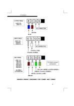
54D CABLE USED ON... CMC1/01 CMC1/10 CMC32/10 CMC34/01 CMC34/10 & CABLE EXTENSIONS
Open the catalog to page 13
Connections and Controls (Wall-mount version) DISCONNECT the mains power to the instrument and the control relays before making changes to connections under the mains terminal safety cover. CDM9 Wall-mount control and connection details (PCB view)
Open the catalog to page 14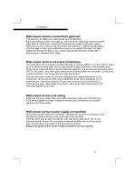
Wall-mount version connections (general) This applies to all cables and cable glands for all installations. After each cable has been connected up, pull most of the cable slack back through the cable gland to prevent any unwanted RF energy being radiated inside the housing. Make sure you do not tension the cable within the instrument. Tighten the cable gland onto the cable so that it grips sufficiently to seal and to prevent the cable from being pulled back through the gland. Any unused cable glands should be sealed with a blanking plug to maintain the IP rating. Wall-mount version cell input...
Open the catalog to page 15
Wall-mount version relay connections Remove the plastic mains cover (unless already removed above) as follows. Squeeze the top of the mounting post with fine pliers or similar and then lift the mains cover away from the terminals. The relay contacts are connected to the I/O terminals only and are not powered from the instrument itself. They must be connected in series with a supply, a load and a 5 Amp fuse. An arc suppressor may be required to prevent excessive electrical noise, depending upon the load. To switch more than 5 Amps will require a slave relay . Feed the relay cable through the inner...
Open the catalog to page 16All LTH Electronics Ltd catalogs and technical brochures
 RBMAG
RBMAG4 Pages
 SGM-200H
2 Pages
 SGM-101F
2 Pages
 Flowmeter
2 Pages
 MXD70 SERIES
20 Pages
 BXD17 Series
12 Pages
 LTH Shortform Brochure
9 Pages
 8000 Series
6 Pages
 2000 Series
6 Pages
 IET40
IET404 Pages
 ECS40 Series
4 Pages
 ECS20 Series
4 Pages
 HD23060
4 Pages
 CMC7 – CMC8
5 Pages
 MLC Series
4 Pages
 Dynaprobe
2 Pages
 HD23050
4 Pages
 PG135
PG1353 Pages
 PME20 WPA1
4 Pages
 9000
90002 Pages
 ECS40
ECS404 Pages
 ECS20
ECS204 Pages
 MTD75
MTD758 Pages
 MXD70 series
16 Pages
 CMC7 AND CMC8 SERIES
5 Pages
 AquaCal 2000
4 Pages
 S400 pH / Redox Electrodes
4 Pages


Archived catalogs
 PMAG
PMAG4 Pages
 SMAG62
4 Pages
 RPL 50 Series
8 Pages
 HOT63
HOT634 Pages
 HPT63 pH / Redox Transmitter
4 Pages
 HET63
HET634 Pages
 SGM100H
4 Pages
 521SMART and 522SMART
2 Pages
 LTH Shortform Brochure
16 Pages
 BC9 Series
3 Pages
 PTU Series
2 Pages
 SGM100F
4 Pages
 SWING
SWING2 Pages


- Flowmeter
- Volume flow monitor
- Liquid flow monitor
- Gas analyzer
- Concentration analyzer
- Monitoring analyzer
- Liquids analyzer
- Waterproof flow meter
- Stainless steel flow monitor
- Industrial flow monitor
- Process analyzer
- Precision flow meter
- Continuous analyzer
- In-line flow meter
- Water flow monitor
- Compact flow monitor
- Oxygen analyzer
- Integration analyzer
- RS485 flow monitor
- Flow meter with display