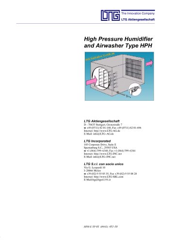
Catalog excerpts
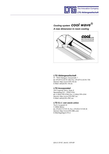
Cooling system cool waveR A new dimension in room cooling LTG Aktiengesellschaft D - 70435 Stuttgart, Grenzstraße 7 +49 (0711) 82 01-180, Fax +49 (0711) 82 01-720 Internet: http://www.LTG-AG.de E-Mail: info@LTG- AG.de - LTG Incorporated 105 Corporate Drive, Suite E Spartanburg S.C., 29303 USA +1 (864) 599- 6340, Fax +1 (864) 599- 6344 Internet: http://www.LTG-INC.net E-Mail: info@LTG- INC.net -
Open the catalog to page 1
Components for Room Air Technology Germany Central Office (Frankfurt) Sales area: PLZ 54, 55, 60, 63, 64, 66-69, 97 Sontraer Str. 27 D-60386 Frankfurt am Main (069) 94 20 19-14, Fax -10 E-mail: Bergmann@LTG-AG.de Central office (Herborn) Sales area: PLZ 30, 31, 34-38, 56, 57, 61, 65 Sperberweg 16 D-35745 Herborn Herr Hartmann (02772) 570-725, Fax -727 E-mail: Hartmann@LTG-AG.de Eastern office (Berlin) Sales area: PLZ 10-25, 29, 39 Eisenhutweg 51a D-12487 Berlin Herr Linke (030) 63 22 87-74, Fax -75 E-mail: Linke@LTG-AG.de Eastern office (Chemnitz) Sales area: PLZ 01-09, 98, 99...
Open the catalog to page 2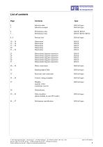
Page Contents Type 4 Selection data KFA/all types 5 Selection example KFA/all types 6 Performance data KFA/E, KFA/S 7 Performance data KFA/T, KFA/F, KFA/L 8...9 Pressure loss KFA/all types 23 Dimensional diagram suspension KFA/E 24 Dimensional diagram suspension KFA/S 25 Dimensional diagram suspension KFA/T 26 Dimensional diagram suspension KFA/F 27 Dimensional diagram suspension KFA/L 28... 32 Water connections KFA/all types 32 Running light (LED) KFA/all types 33 Electronic unit connection KFA/all types 34 ... 36 Control, wiring examples KFA/all types 37 Weights, KFA/all types condensate...
Open the catalog to page 3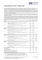
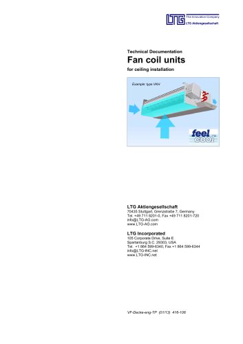
Cooling system cool waveR - Selection data LTG chilled beam with oscillating fan is compact, ceiling-mounted unit which cools the air in a room by convection, making use of the recirculating principle. For reasons of hygiene, it should not be used for dehumidification. The lowest water supply temperature for operation without condensation essentially depends on the humidity of the air and may be 1- 2 K below the dew point of the ambient air. With the cooling fan inoperative, however, a water supply temperature as low as this may cause condensation to form on the heat exchanger plates,...
Open the catalog to page 4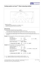
Cooling system cool waveR - Power measuring method Marginal conditions: - determination of room temperature tR at a height of 1.1 m - uniformely distributed heat sources (Q) in the room. Dimensioning The selection may be realized by one of the two methods: 1. Determination of the water inlet temperature and the water flow rate: The cooling capacity diagram (page 6 and 7) will then state the specific cooling capacity Qk/∆t. 2. Determination of the required temperature difference ∆tW (water inlet minus water outlet temp.): The cooling capacity diagram (page 6 and 7) will then indicate the...
Open the catalog to page 5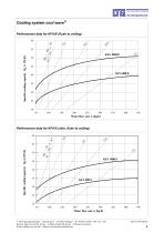
Cooling system cool waveR Performance data for KFA/E (flush to ceiling) 60 Specific cooling capacity Qk/∆t [W/K] Water flow rate w [kg/h] Performance data for KFA/S (slim, flush to ceiling) 60 Specific cooling capacity Qk/∆t [W/K] Water flow rate w [kg/h] E LTG Aktiengesellschaft ⋅ Grenzstraße 7 ⋅ D-70435 Stuttgart ⋅ +49 (0711) 8201-180 ⋅ Fax -720 Internet: http://www.LTG-AG.de ⋅ E-Mail: info@LTG-AG.de ⋅ Printed in Germany ⋅ Former editions are invalid ⋅ Subject to technical modifications.
Open the catalog to page 6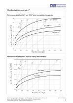
Cooling system cool wave® Performance data for KFA/T and KFA/F (semi-recessed and suspended Water flow rate w [kg/h] © LTG Aktiengesellschaft • GrenzstraBe 7 • D-70435 Stuttgart • « +49 (0711) 8201-180 • Fax -720 Internet: http://www.LTG-AG.de • E-Mail: info@LTG-AG.de • Printed in Germany • Former editions are invalid • Subject to technical modifications.
Open the catalog to page 7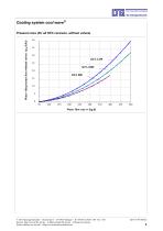
Cooling system cool wave^ Pressure loss (for all KFA versions, without valves) Water flow rate w [kg/h] © LTG Aktiengesellschaft • GrenzstraBe 7 • D-70435 Stuttgart • « +49 (0711) 8201-180 • Fax -720 Internet: http://www.LTG-AG.de • E-Mail: info@LTG-AG.de • Printed in Germany • Former editions are invalid • Subject to technical modifications.
Open the catalog to page 8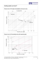
Cooling system cool waveR Pressure loss of LTG angle and straightway valves (per valve) closed valve Water flow rate w [kg/h] Pressure loss of LTG presetting valve with inspection glass 100 80 Water flow rate w [kg/h] E LTG Aktiengesellschaft ⋅ Grenzstraße 7 ⋅ D-70435 Stuttgart ⋅ +49 (0711) 8201-180 ⋅ Fax -720 Internet: http://www.LTG-AG.de ⋅ E-Mail: info@LTG-AG.de ⋅ Printed in Germany ⋅ Former editions are invalid ⋅ Subject to technical modifications.
Open the catalog to page 9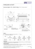
Cooling system cool waveR Dimensional diagram - KFA .../E (flush to ceiling) - Version 1 for flanged installation ceiling panels (option) dim.: max. 100 x max. 20 mm), to be inserted by the customer outlet with solid sheet (standard) W * Distance to the ceiling: 1- mm -2 Avoid any contact between the diffuser and any ceiling components. Legend: X = View from the water supply side (connections M18 x 1.5 - 15° cone) Y = view from the power supply side Size „B“ in mm (between mounting points) 808 1008 „LI“ in mm (overall unit length) approx. 980 approx. 1180 „D“ in mm (length of ceiling...
Open the catalog to page 10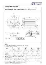
Cooling system cool waveR Dimensional diagram - KFA .../E (flush to ceiling) - Version 2 for flangeless installation ceiling panels (option) dim.: max. 100 mm x 20 mm to be inserted by the customer outlet with solid sheet (standard) Legend: X = View from the water supply side (connections M18 x 1.5 - 15° cone) Y = view from the power supply side Size „B“ in mm (between mounting points) 808 1008 „LI“ in mm (overall unit length) approx. 980 approx. 1180 „D“ in mm (length of ceiling opening) 1006 1206 „LA“ in mm (overall diffuser length) 998 1198 Tolerances - Concerning the values given in...
Open the catalog to page 11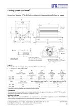
Cooling system cool waveR Dimensional diagram - KFA.../E (flush to ceiling) with integrated boxes for fresh air supply X 382 ca. 309 200 ceiling panels (option) dim.: max. 100 mm x 20 mm to be inserted by the customer outlet with solid sheet (standard) W * Distance to the ceiling: 1- mm -2 Avoid any contact between the diffuser and any ceiling components. Legend: X = view from the water supply side (connections M18 x 1.5 - 15° cone) Y = view from the power supply side Size „B“ in mm (between mounting points) 808 1008 „LI“ in mm (overall unit length) approx. 980 approx. 1180 „d“ in mm max....
Open the catalog to page 12All LTG Aktiengesellschaft catalogs and technical brochures
-
LTG Centrifugal Separators
10 Pages
-
LTG Fibre Compactor
14 Pages
-
LTG Air Distribution
16 Pages
-
LTG Air-Water Systems
32 Pages
-
Product Overview Air Diffusers
28 Pages
-
Swirl Diffusers Type DLA
28 Pages
-
Fancoil Units floor mounted
39 Pages
-
Facade fancoil unit FVD
35 Pages
-
Facade fancoil unit FVS
24 Pages
-
Facade fancoil unit FVM
16 Pages
-
Flow-Rate Controller Type VRE-W
14 Pages
-
Flow-Rate Controller Type VRF-W
16 Pages
-
Flow-Rate Controller Type VRD-W
16 Pages
-
Silencers
10 Pages

