- Catalogs
- LTG Aktiengesellschaft
- Flow-Rate Controller Type VRD-W
- Products
- Catalogs
- News & Trends
- Exhibitions
Flow-Rate Controller Type VRD-W

Flow-Rate Controller Type VRD-W
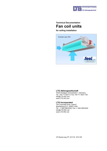
The document provides a comprehensive overview of the Flow Rate Controller VRD-W by LTG Aktiengesellschaft, focusing on its technical specifications, acoustic data, design, functionality, and installation.
Acoustic Data and Casing Sound Emission
Acoustic data is detailed for non-insulated casings, showing sound emission levels across various frequencies for different nominal sizes and air speeds. The data is based on a 6-meter duct with a galvanized sheet steel casing, noting that sound power levels can vary by +/- 6 dB due to resonance effects.
Flow Rate Controller Specifications
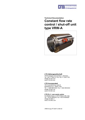
The VRD-W is suitable for constant and variable flow rate control in both high and low-pressure installations. It features two parallel control dampers for supply and return air control, operates independently of initial pressure, and supports a differential pressure range up to 800 Pa with air speeds from 1 to 10 m/s.
Design and Functionality
The controller includes a dynamic differential pressure sensor and an electronic measuring and control unit with a microprocessor. It is equipped with a Belimo LMV-DW-F-MP actuator, integrating a pressure sensor, controller, and actuator. It supports continuous and forced controls with remote adjustment capabilities.
Installation and Operation
Designed for plug-in installation in lock-seam spiral wound ducts per DIN 24145, the VRD-W features factory-wired and hose-connected components. It includes a display of damper settings and an angle scale on the housing, with on-site flow rate settings adjustable via potentiometers on the ZEV setting device.
Technical Characteristics
The controller operates on AC 24 V or DC 24 V with a power consumption of 3 W. It has a maximum sound power level of 35 dB(A) and is maintenance-free. The actuator provides 8 Nm torque and includes a mechanical position indication.
Model Sizes and Dimensions
Model sizes are available with diameters of 100 mm, 125 mm, 160 mm, and 200 mm, each with specific installation lengths.
Optional Accessories
Optional accessories include a galvanized steel casing, insulating case, silencer, and plug-in end pieces with a lip seal gasket.
Catalog excerpts
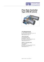
Flow Rate Controller Type VRD-W (short) LTG Aktiengesellschaft D - 70435 Stuttgart, Grenzstraße 7 +49 (0711) 82 01-0, Fax +49 (0711) 82 01-720 Internet: http://www.LTG-AG.de E-Mail: info@LTG- AG.de - LTG Incorporated 105 Corporate Drive, Suite E Spartanburg S.C., 29303 USA +1 (864) 599- 6340, Fax +1 (864) 599- 6344 Internet: http://www.LTG-INC.net E-Mail: info@LTG- INC.net -
Open the catalog to page 1
Components for Room Air Technology Germany Central Office (Frankfurt) Sales area: PLZ 54, 55, 60, 63, 64, 66-69, 97 Sontraer Str. 27 D-60386 Frankfurt am Main (069) 94 20 19-14, Fax -10 E-mail: [email protected] Central office (Herborn) Sales area: PLZ 30, 31, 34-38, 56, 57, 61, 65 Sperberweg 16 D-35745 Herborn Herr Hartmann (02772) 570-725, Fax -727 E-mail: [email protected] Eastern office (Berlin) Sales area: PLZ 10-25, 29, 39 Eisenhutweg 51a D-12487 Berlin Herr Linke (030) 63 22 87-74, Fax -75 E-mail: [email protected] Eastern office (Chemnitz) Sales area: PLZ 01-09, 98, 99 Johannes-Ebert-Straße...
Open the catalog to page 2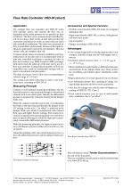
Flow Rate Controller VRD-W (short) Application Accessories and Special Versions The compact flow rate controller unit VRD- W works with auxiliary power and controls the flow rate independent of the initial pressure in two parallel air lines as follows: The flow rate is measured and controlled based on set values, either on the air inlet side (air inlet side controlled ventilation) or on the air outlet side (air outlet side controlled ventilation). The other non- measured air flow is controlled synchronously because of the rigid mechanical connection between the two dampers. This also ensures...
Open the catalog to page 3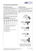
Flow Rate Controller VRD-W (short) Design and Characteristics Installation Conditions The damper has an oval blade of galvanized sheet steel with an EPDM seal meeting DIN EN 1751 Class 3, for ”near gas- tight” sealing of the closed blade. - A straight, undisturbed inflow distance of 1- 3xD(mm) in front of the flow rate controller is required. There are, however, no restrictions regarding the outflow side. Please ensure indicated positioning of the measuring nipples with respect to the air flow. Avoid turbulent air flow and short radius bends or T- branches before the damper. The damper is positioned...
Open the catalog to page 4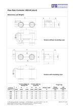
Flow Rate Controller VRD-W (short) Dimensions and Weights B Version without insulating case Version with insulating case Version without insulating case Version with insulating case Weight [kg] Damper angle [º] without insulating case with insulating case E LTG Aktiengesellschaft ⋅ Grenzstraße 7 ⋅ D-70435 Stuttgart ⋅ +49 (0711) 8201-0 Fax -720 Internet: http://www.LTG-AG.de ⋅ E-Mail: [email protected] ⋅ Printed in Germany Former editions are invalid ⋅ Subject to technical modifications.
Open the catalog to page 5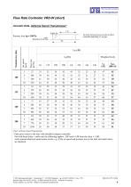
Flow Rate Controller VRD-W (short) Acoustic Data, Airborne Sound Transmission* 1m p is the pressure loss across the air flow controller including a 1 m pipe Chart: Airborne Sound Transmission * Data given refers to the duct with installed compact controller. For both ducts (inlet + outlet air) the following applies: LW total = LW from the chart + 3 dB, with assumed identical sound source levels, e.g. if the air speed and pressure loss in the inlet and outlet ducts are identical. E LTG Aktiengesellschaft ⋅ Grenzstraße 7 ⋅ D-70435 Stuttgart ⋅ +49 (0711) 8201-0 Fax -720 Internet: http://www.LTG-AG.de...
Open the catalog to page 6
Flow Rate Controller VRD-W (short) Acoustic Data, Airborne Sound Transmission* 1m p is the pressure loss across the air flow controller including a 1 m pipe Chart: Airborne Sound Transmission * Data given refers to the duct with installed compact controller. For both ducts (inlet + outlet air) the following applies: LW total = LW from the chart + 3 dB, with assumed identical sound source levels, e.g. if the air speed and pressure loss in the inlet and outlet ducts are identical. E LTG Aktiengesellschaft ⋅ Grenzstraße 7 ⋅ D-70435 Stuttgart ⋅ +49 (0711) 8201-0 Fax -720 Internet: http://www.LTG-AG.de...
Open the catalog to page 7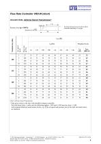
Flow Rate Controller VRD-W (short) Acoustic Data, Airborne Sound Transmission* 1m p is the pressure loss across the air flow controller including a 1 m pipe Chart: Airborne Sound Transmission * Data given refers to the duct with installed compact controller. For both ducts (inlet + outlet air) the following applies: LW total = LW from the chart + 3 dB, with assumed identical sound source levels, e.g. if the air speed and pressure loss in the inlet and outlet ducts are identical. E LTG Aktiengesellschaft ⋅ Grenzstraße 7 ⋅ D-70435 Stuttgart ⋅ +49 (0711) 8201-0 Fax -720 Internet: http://www.LTG-AG.de...
Open the catalog to page 8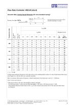
Flow Rate Controller VRD-W (short) Acoustic Data, Casing Sound Emission (for non-insulated casing)* 1m p is the pressure loss across the air flow controller including a 1 m pipe < ≙ <15 dB Casing sound emission data given in the chart refers to the emitting jacket surface of a duct of galvanized sheet steel, total length 6 m, with the flow rate controller installed. Due to resonance effects given frequency- related sound power level data may vary by +/- 6 dB max. Chart: Casing sound emission * Data given refers to the duct with installed compact controller. For both ducts (inlet + outlet air)...
Open the catalog to page 9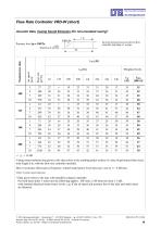
Flow Rate Controller VRD-W (short) Acoustic Data, Casing Sound Emission (for non-insulated casing)* 1m p is the pressure loss across the air flow controller including a 1 m pipe < ≙ <15 dB Casing sound emission data given in the chart refers to the emitting jacket surface of a duct of galvanized sheet steel, total length 6 m, with the flow rate controller installed. Due to resonance effects given frequency- related sound power level data may vary by +/- 6 dB max. Chart: Casing sound emission * Data given refers to the duct with installed compact controller. For both ducts (inlet + outlet air)...
Open the catalog to page 10
Flow Rate Controller VRD-W (short) Acoustic Data, Casing Sound Emission (for non-insulated casing)* 1m p is the pressure loss across the air flow controller including a 1 m pipe < ≙ <15 dB Casing sound emission data given in the chart refers to the emitting jacket surface of a duct of galvanized sheet steel, total length 6 m, with the flow rate controller installed. Due to resonance effects given frequency- related sound power level data may vary by +/- 6 dB max. Chart: Casing sound emission * Data given refers to the duct with installed compact controller. For both ducts (inlet + outlet air)...
Open the catalog to page 11All LTG Aktiengesellschaft catalogs and technical brochures
 Shut-off damper KLB
8 Pages
 Decentralised ventilation units
12 Pages
 LTG Air-Water Systems
22 Pages
 LTG Centrifugal Separators
10 Pages
 LTG Fibre Compactor
14 Pages
 LTG Air Distribution
16 Pages
 LTG Air-Water Systems
32 Pages
 Product Overview Air Diffusers
28 Pages
 Swirl Diffusers Type DLA
28 Pages
 LTG cool wave®
53 Pages
 Fancoil Units floor mounted
39 Pages
 Facade fancoil unit FVD
35 Pages
 Facade fancoil unit FVS
24 Pages
 Facade fancoil unit FVM
16 Pages
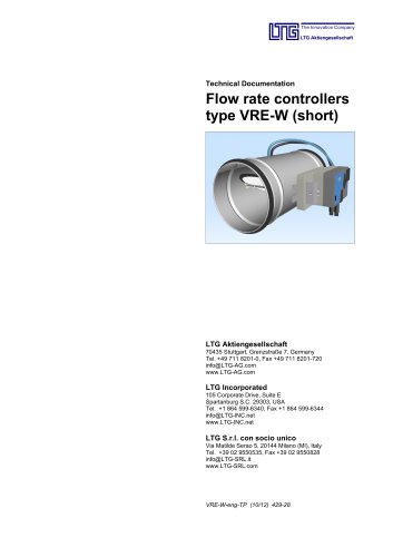 Flow-Rate Controller Type VRE-W
14 Pages
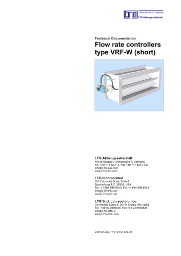 Flow-Rate Controller Type VRF-W
16 Pages
 Silencers
10 Pages


Archived catalogs


- Valve
- Stainless valve
- On/off valve
- Pressure limiter
- Propeller fan
- Butterfly valve
- Air circulation fan
- Industrial fan
- Industrial pressure limiter
- Air blower
- Industrial use filter
- Steel valve
- AC fan
- Single-stage blower
- Centrifugal blower
- Centrifugal classifier
- Steel fan
- Electrically-powered fan
- Liquids separator
- Air valve