


Shaft Locking Devices catalog

Shaft Locking Devices catalog
Lovejoy Shaft Locking Devices (SLDs) offer a keyless mechanical interference fit to connect hubs to shafts, ensuring torque transmission and withstanding axial thrust. This is achieved through screw tension that converts into radial pressure, creating a zero backlash connection that is easily releasable.
Features and Benefits
- No backlash due to precise fit tolerances.
- Adjustable axial position and angular timing.
- Higher contact pressures for enhanced torque transmission.
- Easy installation and removal without component damage.
Design Benefits
- Eliminates the need for machining keyways or splines.
- Reduces shaft stress, allowing for smaller diameter shafts.
- Facilitates easier maintenance.
Safety Instructions
Adherence to safety instructions is crucial to prevent severe injury or death. Proper selection, sizing, and installation are essential, and suitable guards must be installed according to OSHA and ASME standards.
SLD Series Specifications
- SLD 900: Self-centering, suitable for hollow shafts, torque range 22 - 118,010 ft-lb.
- SLD 1500: Medium high torque, self-releasing, torque range 170 - 565,563 ft-lb.
- SLD 1850: High torque, self-centering, torque range 273 - 44,625 ft-lb.
- SLD 2600: Heavy duty, very high torque, torque range 532 - 155,461 ft-lb.
Applications
SLDs are used in various applications including gearboxes, conveyors, fans, pumps, and more.
Selection Process
Selection involves determining shaft diameter or maximum torque, and using tables to verify compatibility. The hub must withstand pressure without yielding, calculated using specific formulas.
Combined Torque and Axial Loads
Adjustments are necessary for axial loads, with coefficients of friction and duty factors considered for accurate torque transmission.
This document provides detailed specifications and dimensional data for various series of shaft locking devices, including the SLD 900, SLD 1500, and SLD 1850 series. These devices secure components on a shaft without the need for keyways or other mechanical locking methods.
SLD 900 Series
The SLD 900 series includes a range of sizes with specific dimensional data such as outer diameter (D), shaft diameter (ds), and maximum transmissible torque (Mt). The series is characterized by its use of locking screws and specific torque requirements for secure installation.
SLD 1500 Inch Series
This series provides specifications for shaft locking devices in inch measurements. Key parameters include the outer diameter (D), shaft diameter (d), and maximum transmissible axial force (F). The series also details the pressure on the hub (pH) and shaft (pS), along with the required screw tightening torque (MA).
SLD 1500 Metric Series
Similar to the inch series, the metric series offers specifications in metric units. It includes data on maximum pressures, locking screw specifications, and transmissible forces and torques.
SLD 1850 Inch Series
This series provides detailed dimensional data for larger shaft locking devices, focusing on maximum transmissible axial force and torque. It also includes information on the pressure exerted on the hub and shaft, as well as the required screw specifications.
Key Parameters and Specifications
- Outer Diameter (D): The external diameter of the shaft locking device.
- Shaft Diameter (d): The diameter of the shaft that the device is designed to fit.
- Maximum Transmissible Torque (Mt): The maximum torque that can be transmitted through the device.
- Locking Screws: Specifications for the screws used to secure the device, including size and tightening torque.
- Pressure on Hub and Shaft (pH, pS): The pressure exerted on the hub and shaft during operation.
Conclusion
The document serves as a comprehensive guide for selecting and installing shaft locking devices, providing essential data for ensuring proper fit and function in various applications.
Catalog excerpts

JW JW JW JIS CJ SF MC MC MC G G G ■■ Low Torque Series SLDS SF SF ■■ Self-Centering Series SLDS CJ CJ In This Section: JIS JIS Shaft Locking Devices HP HP ■■ High Torque Series SLDS HP ■■ Medium Torque Series SLDS ■■ Heavy Duty Series SLDS GD GD GD D D D SP SP SP T T T UJ UJ UJ VSD VSD VSD R R R SLD SLD SLD ED ED ED www.lovejoy-inc.com 425 SLDSLD-1
Open the catalog to page 1
SF SF SF MC MC MC G G G HP CJ CJ CJ JIS JIS JIS JW JW JW Shaft Locking Devices HP HP Safety Warning When using Lovejoy products, you must follow these instructions and take the following precautions. Failure to do so may cause the power transmission product to break and parts to be thrown with sufficient force to cause severe injury or death. GD GD GD D D D T T T SP SP SP Refer to this Lovejoy Catalog for proper selection, sizing, horsepower, torque range, and speed range of power transmission products, including elastomeric elements for couplings. Follow the installation instructions included...
Open the catalog to page 2
Shaft Locking Devices JIS CJ CJ Lovejoy Shaft Locking Devices expand to fill the gap between the shaft and hub, allowing for easy installation and removal, saving time over traditional interference fit techniques. The contact pressures created using a Shaft Locking Device can be greater than traditional interference fit pressures, allowing for more torque to be transmitted or shorter hubs to be used. The easy installation also allows the hub to be positioned more accurately on the shaft, and can facilitate angular timing of the hub. SF SF Lovejoy Shaft Locking Devices connect hubs solidly to...
Open the catalog to page 4
Shaft Locking Devices Overview JW Metric 14mm to 240mm Larger sizes on request 22 - 118,010 ft-lb CJ Metric shafts 18mm to 200mm Inch shafts 3/4 to 4 inch Larger sizes on request 259 - 40,274 ft-lb ■■ High torque ■■ Exceptional concentricity ■■ Self-centering ■■ Axial hub position fixed during clamping Metric shafts 18mm to 200mm Inch shafts 3/4 to 4 inch Larger sizes on request 203 - 34,151 ft-lb ■■ Heavy duty ■■ Very high torque ■■ Self-centering ■■ Exceptional concentricity Metric shafts 25mm to 240mm Inch shafts 1 to 6-1/2 inch Larger sizes on request 532 - 155,461 ft-lb ■■ Medium torque...
Open the catalog to page 5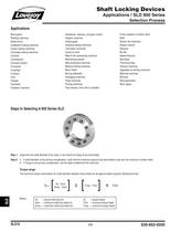
^ world turns for COljg* Shaft Locking Devices Selection Process Bevel gears Braiding machines Brake drums Cardboard making machines Carpet making machines Chocolate making machines Conveyor pulleys Footwear machines Gearboxes, reducers, and gear motors Graphic machines Helical gears Industrial sewing machines Lamination machines Levers & cams Meat & fish processing machines Mechanical presses Milk processing machines Milling & drilling machines Mixer shafts Moving sidewalks Packaging machines Pasta machines Printing machines Pulp industry: drive rolls & cylinders Pump impellers & turbine rotors...
Open the catalog to page 6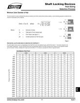
Shaft Locking Devices Selection Process Minimum Outer Diameter of Hub The hub must be of a size to withstand the pressure exerted by the Shaft Locking Device without yielding. Use the following equations to determine the minimum hub diameter (Dmin) required. Yield point of hub material (psi) Form factor (see figure 1.) Alternatively, use the table below to determine the Coefficient K. To use the table, find the column corresponding to the Yield Point of the hub material (in psi), and the Form factor "f" from above (based on the hub's length through bore). Use the row with the pH from the specification...
Open the catalog to page 7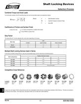
^ world turns for COljg* Shaft Locking Devices Selection Process Combined Torque and Axial Loads If an axial load is present, then the resulting torque that can be transmitted needs to be adjusted as follows: shaft diameter (inches) maximum torque for device (ft-lbs) Coefficients of Friction and Surface Finish Lovejoy SLD uses u = 0.12 which corresponds to a slightly oiled surface Duty Factor The values Mt and F must be adjusted with a duty factor depending on the setup: Multiple Shaft Locking Devices Used in Series If more than one Shaft Locking Device is used, the transmissible torque must...
Open the catalog to page 8
Shaft Locking Devices Dimensional Data L = total width of thrust rings (relaxed state) B = width of thrust rings (relaxed state) T = locking screw specifications MA = screw tightening torque e = width of gap (relaxed state) D = outer diameter of disc C = maximum diametrical clearance (difference between hub diameter and shaft diameter) Mt = maximum transmissible torque SLD 900 Series Dimensional Data
Open the catalog to page 9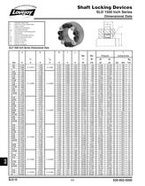
Shaft Locking Devices Dimensional Data L = total width (relaxed state) B = width of thrust rings (relaxed state) T = locking screw specifications M/\ = screw tightening torque D = outer diameter of shaft locking device F = maximum transmissible axial force Mt = maximum transmissible torque SLD 1500 Inch Series Dimensional Data
Open the catalog to page 10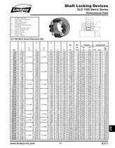
*e«otW turns for couy Shaft Locking Devices Dimensional Data L = total width (relaxed state) B = width of thrust rings (relaxed state) T = locking screw specifications MA = screw tightening torque D = outer diameter of shaft locking device F = maximum transmissible axial force Mt = maximum transmissible torque SLD1500 Metric Series Dimensional Data
Open the catalog to page 11
Shaft Locking Devices Dimensional Data L = total width (relaxed state) B = width of thrust rings (relaxed state) T = locking screw specifications = screw tightening torque D = outer diameter of shaft locking device F = maximum transmissible axial force Mt = maximum transmissible torque SLD 1850 Inch Series Dimensional Data
Open the catalog to page 12
Shaft Locking Devices Dimensional Data L = total width (relaxed state) B = width of thrust rings (relaxed state) T = locking screw specifications = screw tightening torque D = outer diameter of shaft locking device F = maximum transmissible axial force Mt = maximum transmissible torque SLD 1850 Metric Series Dimensional Data
Open the catalog to page 13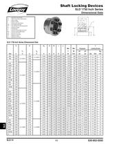
Shaft Locking Devices Dimensional Data L = total width (relaxed state) B = width of thrust rings (relaxed state) T = locking screw specifications = screw tightening torque D = outer diameter of shaft locking device F = maximum transmissible axial force Mt = maximum transmissible torque SLD 1750 Inch Series Dimensional Data
Open the catalog to page 14All Lovejoy catalogs and technical brochures
 Torsional
42 Pages
 HercuFlex Gear Couplings
28 Pages
 Lovejoy Hydraulics
24 Pages
 RunRight by Lovejoy Catalog
68 Pages
 HercuFlex Couplings Catalog
28 Pages
 QUICK FLEX® Couplings
56 Pages
 Grid catalog
19 Pages
 High Performance Gear Catalog
20 Pages
 Jaw
Jaw28 Pages
 4 BOLT DISC COUPLING
2 Pages
 Disc
Disc28 Pages
 Universal Joints Catalog
12 Pages
 Specialty Products Catalog
28 Pages
 Curved Jaw Couplings Catalog
22 Pages
 Stainless Steel Jaw Catalog
2 Pages
 Complete Lovejoy Catalog
522 Pages
 HydraulicReservoir
24 Pages
 LH COUPLINGS
2 Pages
 Motion Control Catalog
22 Pages
 Jaw In-Shear
8 Pages
 4 Bolt Disc Catalog
2 Pages
 Disc Catalog
28 Pages
 Jaw Type Catalog
28 Pages
 Lovejoy / Sier-Bath Gear Catalog
78 Pages
 FARR Gear Catalog
7 Pages
 Stainless Steel Jaw
2 Pages
 Torsional catalog
42 Pages
 Specialty catalog
28 Pages
 Universal Joint catalog
12 Pages
 BNZ Cooler Catalog
32 Pages
 Pump/Motor Mount Catalog
24 Pages
 Motion Control Couplings
22 Pages
 Gear catalog
78 Pages
 Curved Jaw catalog
22 Pages
 Jaw In-Shear catalog
8 Pages
 L-LOC Clamp Feature
1 Page


Archived catalogs
 RunRight Products Catalog
68 Pages
 Jaw Coupling
28 Pages
 S-Flex
22 Pages
 Full Line Catalog
56 Pages
 S-Flex catalog
22 Pages
 Engineering Data
24 Pages
 FARR Rigid Couplings
6 Pages

- Fitting
- Hydraulic fitting
- Vessel
- Metal fitting
- Heat exchanger unit
- Flexible coupling
- Shaft shaft coupling
- Industrial tank container
- Vertical tank
- Liquid/liquid heat exchanger
- Flange coupling
- Anti-vibration mount
- Torque coupling
- Tubular heat exchanger
- Rigid coupling
- Zero-backlash shaft coupling
- Transmission coupling
- Metal anti-vibration mount
- Sleeve coupling
- Compact coupling