
- Catalogs
- Logic S.r.l.
- ECS-R / ECS-RF

ECS-R / ECS-RF

ECS-R / ECS-RF
The Earthing Monitoring System is designed to meet the ATEX Directive 2014/34/EU requirements for use in ATEX Zone 1/21, with the IS1 clamp suitable for ATEX Zone 0/20. The ECS-R and ECS-RF devices ensure the earth connection of process equipment such as IBCs, drums, and road tankers, with real-time monitoring to maintain an electrical resistance of 10 Ω or less, as per ATEX standards. The system includes two Ex i outputs for remote LEDs on the clamp, indicating connection status with a green LED for consensus and a red LED for non-consensus.
Device Specifications
The ECS-RF model includes an interlock SPST N.O. contact with a safety integrity level up to SIL2, compliant with EN 50495. The devices are marked for gases, vapors, mists, and dust with specific ATEX markings and are suitable for temperatures ranging from -20 °C to +55 °C. The clamp input and output LED specifications include voltage, current, power, capacitance, and inductance values.
Order Codes
- ECS-R: Equipped with signaling contact
- ECS-RF: Equipped with SIL2 interlock contact
ATEX Marking
- Gases, vapors, mists: II 2(1)G Ex d[ia Ga] IIC T6 Gb
- Dust: II 2(1)D Ex tb[ia Da] IIIC T85°C Db
Power and Dimensions
The system operates on a 230 Vac ± 5% power supply and uses a standard 6-wire spiral cable according to IEC 60332-1-2. The device dimensions are 195 x 195 x 148 mm.
Application Examples and Models
The document lists models ECS-R (non-SIL) and ECS-RF (SIL 2) with application examples and additional components like SP5/SP10 and CR20.
Catalog excerpts
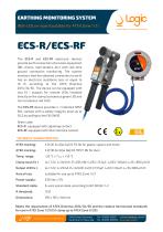
EARTHING MONITORING SYSTEM] With LED on-board suitable for ATEX Zone 1/21 The ECS-R and ECS-RF electronic devices provide earth connection of process equipment (IBC, drums, road tankers, etc.) with real-time ground connection monitoring. The system monitors that the obtained connection to earth has an electrical resistance less or equal to 10 O, according to the ATEX Directive 2014/34/EU. The device can be equipped with two Ex i outputs for remote LEDs installed directly on the clamp (consensus green LED and non consensus red LED). The ECS-RF device provides n. 1 interlock SPST N.O. contact with a safety integrity level up to SIL2 according to the EN 50495. Order code: ECS-R: equipped with signaling contact ECS-RF: equipped with SIL2 interlock contact TECHNICAL CHARACTERISTICS ATEX marking: ATEX marking: Temp. range: Clamp input Ex i: Output LED Ex i: Area of use: Power supply: Standard cable: R threshold: Dimensions: II 2(1)G Ex d[ia Ga] IIC T6 Gb for gases, vapors and mists II 2(1)D Ex tb[ia Da] IIIC T85°C Db for dust -20 °C £ Tamb £ +55 °C Uo=7.2V, I0=345mA, P0=621mW, G(NC)=13.5|iF, Lq(IIC)=149|jH, L0/R0=860 |iH/O U0=7.2V, Ic=23mA, Po=42mW, Cq(IIC)=13.5^F, Lq(IIC)=34^H, Lq/Rq=860 |iH/O suitable for use up to ATEX Zone 1/21 230 Vac±5% 6-wire spiral cable, according to IEC 60332-1-2 10 O 195 x 195 x 148 mm Meets the requirement of ATEX Directive 2014/34/EU and the relative harmonized standards for use in ATEX Zone 1/21 (IS1 clamp up to ATEX Zone 0/20). 27020 Travaco Siccomario Via delTovo 5/3 Pavia Italy commercialeialogic-pavia.it www.logic-pavia.it
Open the catalog to page 1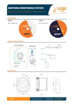
EARTHING MONITORING SYSTEM With LED on-board suitable for ATEX Zone 1/21 MEMBRANES Model: APPLICATION EXAMPLES ECS-R/ECS-RF
Open the catalog to page 2

- Panel PC
- Industrial panel PC
- Panel PC with touch screen
- Force sensor
- LCD panel PC
- Housed panel PC
- Tension/compression force transducer
- Windows 10 panel PC
- Steel load cell
- Strain gauge force sensor
- Wireless panel PC
- Windows panel PC
- Stainless steel force transducer
- HMI panel PC
- Weighing force transducer
- Liquids dispensing system
- Beam type force sensor
- Stainless steel balance
- Platform balance
- Compression force transducer