


Gear Cutting Tools and Knowledge Catalog
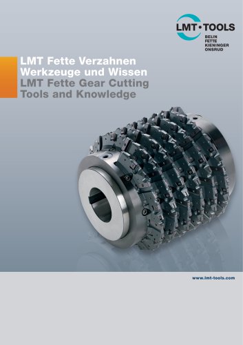
Gear Cutting Tools and Knowledge Catalog
The document introduces the "LMT Fette Gear Cutting – Tools and Knowledge" catalogue, aligning with the new LMT catalogue concept. It serves as a product guide for gear cutting tools, offering structured selection criteria, symbols, and application recommendations.
LMT Tools combines expertise in precision tool technology, covering industries like automotive, aerospace, and energy. Core competencies include gear cutting, threading, milling, and reaming, supplemented by services like project engineering and training.
SpeedCore is a new substrate for hobs, offering increased hot hardness and cutting speeds 30% higher than traditional hobs, improving productivity and process reliability.
Spur gear hobs are detailed in DIN 8000, with classifications based on accuracy. Special tolerance restrictions apply for higher quality requirements.
Tolerance values for hobs are provided in 1/1000 millimeters across various modules.
Optimization of hobs focuses on balancing cutting time, tool life, and gear quality. High-performance hobs should maintain or improve gear quality while reducing machining times.
Important parameters include module, number of teeth, helix angle, and cutting depth. Tip chip thickness is critical for hob design and optimization.
Increasing the number of gashes extends tool life, while coating high-performance hobs allows for higher cutting speeds and feeds.
Coarse shifting increases tool life by allowing better observation of wear development.
Machining time is influenced by gear width, number of teeth, and cutting speed. High axial feeds and multi-start hobs reduce machining time but increase tip chip thickness.
Gear quality depends on machine accuracy, hob quality, and stable workpiece clamping.
Controlling feed marks depth ensures gear quality. Compliance with DIN 3968 or comparable standards is necessary.
Optimization considers the entire system, including the hobbing machine and cutting parameters. High-performance hobs should be tailored to specific applications.
Detailed descriptions include module, pressure angle, helix angle, and material.
Key parameters include cutting speed, feed, and shift increment. Results include tool life quality and machining time per workpiece.
Objectives include shorter machining times and better gear quality, supplemented by qualitative and quantitative specifications.
Limits include maximum cutter diameter, length, spindle, and table speed.
Includes a pictogram description and an inquiry form for hob customization.
Heavy-duty roughing hobs are designed with vertically staggered teeth for efficient metal removal and even load distribution.
The LMT Fette heavy-duty roughing hob achieves high cutting capacities and can be used as a finishing tool.
Carbide types K and P are compared, with K-carbides requiring full coating.
Dry machining with carbide hobs can reduce gear production costs and allow higher cutting speeds.
Includes tables listing specifications for different hob models.
Discusses dry and wet machining, highlighting the impact of cooling lubricants on tool life and machining efficiency.
Dry machining allows higher cutting speeds due to the absence of cooling lubricants.
Emphasizes correct tool design and cutting parameters for effective heat dissipation during dry machining.
Recommends maintaining a minimum tip chip thickness for effective heat dissipation.
Advantages include chip removal and cooling, while disadvantages include increased costs and health risks.
HSC offers high surface quality and reduced machining times.
Solid carbide tools are used for gear manufacturing with cutting speeds varying by module size.
Flank wear is the primary wear form on carbide hobs, with recommendations for re-coating after regrinding.
Includes a size table for solid carbide hobs.
Skiving hobs are used for machining rough-milled and hardened gears, with designs including solid carbide and indexable carbide inserts.
Skiving hobs feature a negative tip rake angle for a peeling cut.
Skiving hobs eliminate hardening distortion and improve gear quality.
Cutting speed depends on module size and gear hardness, with specific feed rates for finishing and roughing.
Intensive cooling with cutting oils is essential for skiving hobs.
Wear mark width should not exceed 0.15 mm to prevent quality losses.
Shifting distributes wear evenly over cutting edges.
Tool life depends on module size and material hardness.
Quality depends on hob material, machine stability, and cutting speed.
Modern machines offer better conditions for quality gear cutting.
Skiving hobs should be sharpened when wear mark reaches 0.15 mm.
The ChamferCut system allows gear cutting and deburring on one machine.
Discusses the ChamferCut tool system for optimizing gear production.
Tools are clamped on one arbor, with production controlled by software.
Application is determined by the spatial conditions of the hobbing machine.
Includes tables listing specifications for various hobs.
Hobs are used for manufacturing compressor rotors, emphasizing accuracy and maintenance.
Outlines specifications for worm gear hobs, emphasizing pitch cylinder diameter.
Flank form is determined by the worm's flank form, standardized in DIN 3975.
Worm gear hobs are available in radial and tangential designs.
Shaving worms are used for high-precision worm gears.
Modern CNC machines allow for economical tool use.
Determined by module, number of teeth, and profile shift.
Worm gear hobs can be manufactured as bore or shank hobs.
Outlines specifications for selecting between bore-type and shank-type hobs.
Determined by variables like module and number of teeth.
Provides a diagram to determine the appropriate hob type.
Must be adapted to the technical data of the drive worms.
Highlights benefits like quick availability and economic efficiency.
Hobs consist of a cutter body with screwed-on tooth segments.
Overview of gear milling cutters with indexable carbide inserts.
Describes the arrangement of indexable carbide inserts on gear milling cutters.
Includes specifications for different module sizes.
Benefits include lower machining costs and improved gear cutting quality.
Includes specifications for tools and machines.
Described as productive, innovative, and reliable.
Comparison of gear milling cutters and hobs, emphasizing cost-effectiveness.
Comparison and specifications of gear milling cutters and hob cutters with indexable inserts.
Gear milling cutters are available in modules ranging from 6 to 70.
Discusses machining methods for gears with large modules.
References several standards for gear profiles and quality grades.
Segmented gear milling cutter offers advantages like short tool change times.
Includes tables listing gear milling cutter specifications.
Detailed specifications for gear milling cutters with indexable inserts.
Outlines recommended cutting data for involute roughing.
Includes tables comparing pitch, module, and tolerances.
Provides recommendations for power requirements and cutting conditions.
Includes attachments on various topics like cutter deviations and tool holding.
Discusses quality assessment of hobs and gears, referencing DIN standards.
Emphasizes the importance of contact ratio deviation for assessing hob quality.
Describes tool holding methods for torque transmission and tool location.
Details various hob clamping methods.
Explains profiles of spur gears with involute teeth.
Outlines basic profiles for spur gears with involute teeth.
Standardized basic profiles are detailed in DIN 867 and ISO 53.
Describes derivation of basic hob profiles from spur gear profiles.
Basic hob profile should not contain modifications like chamfers.
Provides detailed measurements for various profiles.
Guidelines on cutting conditions for gear hobbing.
Choice of cutting conditions should consider interrelation between workpiece, hob, and machine.
High feeds are selected for roughing operations, while finishing requires specific cutting conditions.
Gear hobs are made from KHSS-E and carbides.
Assessed based on cutting speed, tool life quality, and wear mark widths.
Diagram shows cutting speed as a function of module and machinability.
Emphasizes importance of selecting appropriate cutting conditions.
Specifications
Detailed specifications for cutting conditions in gear hobbing.
Provided for both coated and uncoated hobs.
Specified in mm per workpiece rotation.
Critical factor in determining hob stress and tool life.
Relationship between number of starts, axial feed, and machining time.
Table demonstrates optimization for different gear examples.
High axial feed is recommended for economic reasons.
Emphasizes balancing efficiency with precision.
Penetration curve in gear hobbing is influenced by several factors.
Outlines procedures for calculating approach distances.
Recommendations for maintenance of hobs.
Discusses wear phenomena on hob teeth.
Figures illustrate relationship between wear and number of workpieces cut.
Discusses maintenance of hobs, focusing on wear mark widths.
Wear distribution is crucial for economic operation.
Specifies requirements for the cutting face grinder.
Tolerances for single-start hobs are specified in DIN 3968.
Emphasizes importance of keeping radial and axial runouts small.
Discusses cumulative pitch deviation of gashes.
Measurements can be conducted using an indexing plate.
Tolerances for gash lead deviations are based on a 100 mm measuring distance.
Regrinding of roughing hobs is possible on any hob regrinding machine.
Operations aim to achieve a smooth transition to the reground tooth tip portion.
Hobs with protuberance have projections on the tooth tips.
Discusses wear phenomena observed on hobs used in gear cutting.
Understanding cross-sectional areas of cut is crucial for studying wear behavior.
Identifies different types of wear on hob teeth.
Discusses how cutting conditions affect tool wear.
Categorizes factors influencing hob wear.
Explains necessity of defining tool/workpiece penetration curve.
Discusses technical aspects of gear hobbing.
Factors such as cutting speed and tool material pairing are considered.
Wear on the hob is categorized into tip wear and flank wear.
Formulas are provided for calculating penetration curve.
Describes computational process for determining chip geometry.
Suggests matching angle and shape of lead to conditions.
Discusses method of involute gear cutting using indexable inserts.
Continuous indexable cutting inserts allow for entire profile height to be finish-milled.
Provides recommended values for power requirements during involute roughing.
Lists various materials and their power factors.
References several DIN standards.
Part of a catalog series titled "Tools and Knowledge" by LMT Tools.
Catalog excerpts

LMT Fette Verzahnen Werkzeuge und Wissen LMT Fette Gear Cutting I Tools and Knowledge
Open the catalog to page 1
Impressum Herausgeber: LMT Tool Systems GmbH & Co. KG, Grabauer Strasse 24, 21493 Schwarzenbek, Deutschland, Telefon: +49 41 51 12-0 Verantwortlich i. S. d. P.: Norman Winter Gestaltung: deckermedia GbR, Rostock Druck: Weidner GmbH, Rostock Imprint Publisher: LMT Tool Systems GmbH & Co. KG, Grabauer Strasse 24, 21493 Schwarzenbek, Germany, phone: +49 41 51 12-0 Responsible according to the press law.: Norman Winter Design: deckermedia GbR, Rostock Printed by: Weidner GmbH, Rostock © by LMT Tool Systems GmbH & Co. KG Nachdruck, auch auszugsweise, ist nur mit unserer Zustimmung gestattet. Alle...
Open the catalog to page 2
Vorwort Foreword Wälzfräser für Stirnräder HSS/SpeedCore Hobs for spur gears HSS/SpeedCore Der neue Schneidstoff – eine Klasse für sich The new cutting material – in a class of its own Wälzfräser für Stirnräder Hartmetall Carbide hobs for spur gears Wälzfräser zur Herstellung von geradeund schrägverzahnten Stirnrädern mit Evolventenflanken Hobs for producing straight- and helical-tooth spur gears with involute flanks Werkzeugsysteme ChamferCut Tool systems ChamferCut Hinweise zu den Beschreibungen und Baumaßtabellen für Stirnrad-Wälzfräser Notes to the descriptions and tables for spur gear hobs...
Open the catalog to page 3
Vorwort Foreword Sehr geehrte Kunden und Interessenten, Dear customers and potential customers, mit dem neu strukturierten und gegliederten Katalog „LMT Fette Verzahnung – Werkzeuge und Wissen“ setzten wir unser neues LMT-Katalogkonzept konsequent fort. the newly structured catalogue “LMT Fette Gear Cutting – Tools and Knowledge” consistently pursues the new LMT catalogue concept. Seit mehreren Jahrzehnten produzieren wir erfolgreich Werkzeuge für die Zahnradbearbeitung. Innovative Entwicklungen wurden von uns zur Serienreife gebracht, um den immer weiter steigenden Anforderungen gerecht zu werden....
Open the catalog to page 4
LMT Tools bündelt die Kompetenzen führender Spezialisten aus der Präzisionswerkzeugtechnik. Auf dieser Basis entwickelt und liefert LMT Tools weltweit Werkzeuglösungen zur Bearbeitung von hochfesten Stahlwerkstoffen bis hin zu Composite-Materialien. LMT Tools combines the competences of leading specialists in the field of precision tool technology. This pooled expertise enables LMT Tools to develop and deliver tool solutions worldwide for processing materials ranging from high-strength steel to composite materials. Das umfangreiche Produktprogramm bietet perfekte Lösungen für die Branchen Automotive,...
Open the catalog to page 5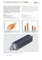
Der neue Schneidstoff – eine Klasse für sich The new cutting material – in a class of its own Mit SpeedCore wurde ein neues Substrat für Wälzfräser entwickelt. Die gesteigerte Warmhärte dieses intermetallischen Schneidstoffs ermöglicht min. 30 % höhere Schnittgeschwindigkeiten gegenüber HSS-PM4/14-Wälzfräsern und damit kürzere Fertigungszeiten ohne Einbußen bei den Standwegen und kommt den Anforderungen der Kunden nach unkomplizierter Handhabung und einfacher Wiederaufbereitung entgegen. Durch die Kombination des neuen Substrats SpeedCore mit einer maßgeschneiderten Beschichtung werden Spitzenleistungen...
Open the catalog to page 6
Wälzfräser zur Herstellung von gerade- und schrägverzahnten Stirnrädern mit Evolventenflanken Hobs for producing straight- and helical-tooth spur gears with involute flanks Die geometrischen Grundbegriffe eines Stirnrad-Wälzfräsers zur Erzeugung von Zahnrädern mit Evolventenflanken sind in DIN 8000 festgelegt und ausführlich erläutert. Danach ist der geometrische Ausgangskörper eines Wälzfräsers immer eine Schnecke. Wird nun diese Schnecke mit Spannuten versehen, erhält man die Fräserzähne. Diese werden durch das sogenannte „Hinterarbeiten“ schnittfähig. The fundamental geometrical concepts of a...
Open the catalog to page 7
Walzfraser zur Herstellung von gerade- und schragverzahnten Stirnradern mit Evolventenflanken Hobs for producing straight- and helical-tooth spur gears with involute flanks Erreichbare Radqualitaten Attainable gear qualities In DIN 3968 sind die zulassigen Abweichungen fur eingangige Walzfraser festgelegt. Dabei handelt es sich um 16 Einzelabweichungen, die z. T. von-einander abhangig sind, und um eine Sammelabweichung. Als Sammelabweichung ist die Eingriffsteilungsabweichung Fe innerhalb eines Eingriffsbereiches die aussagekraftigste GroBe bei der Beurteilung der Walzfraserqualitat. Sie gestattet...
Open the catalog to page 8
Hinweise zu den Beschreibungen und Baumaßtabellen für Stirnrad-Wälzfräser Notes to the descriptions and size tables for spur gear hobs Baumaße Die vier Hauptabmessungen der Wälzfräser sind in der folgenden Reihenfolge festgelegt: Fräserdurchmesser, Schneidenlänge, Gesamtlänge und Bohrungsdurchmesser; z. B. für Modul 8, Kat.-Nr. 2032: Ø 125 × 130/138 × Ø 40. Abweichende Baumaße können erforderlich werden aufgrund der Werkstückform, wegen der Begrenzung der Fräserbaumaße, durch die Abmessungen und Leistung der Wälzfräsmaschine. Ebenso durch die Abmessungen der vorhandenen Fräserdorne oder zur Erzielung...
Open the catalog to page 9
Hinweise zu den Beschreibungen und Baumaßtabellen für Stirnrad-Wälzfräser Notes to the descriptions and size tables for spur gear hobs Kopfflankeneinzug Wenn ein Radpaar unter Last läuft, soll der Kopfflankeneinzug den Eintrittsstoß verringern oder vermeiden. Für die Auslegung des Wälzfräser-Bezugsprofils sind die vollständigen Verzahnungsdaten bzw. die Werkstückzeichnung erforderlich. Die Größe des erzeugten Flankeneinzugs ist, ähnlich wie beim Kantenbruch, von der Zähnezahl abhängig. Profile modification The purpose of the profile modification is to reduce or avoid the interference when the teeth...
Open the catalog to page 10All LMT Tools catalogs and technical brochures
 PCD Tools Brochure
4 Pages
 ChamferCut Brochure
6 Pages
 Rasant Steel Brochure
12 Pages
 UNIFY Brochure
3 Pages
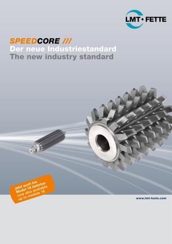 SpeedCore Hobs Brochure
6 Pages
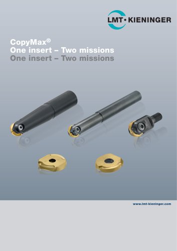 CopyMax Brochure
12 Pages
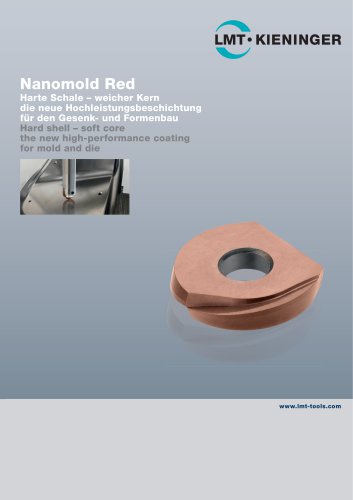 Nanomold Red Brochure
4 Pages
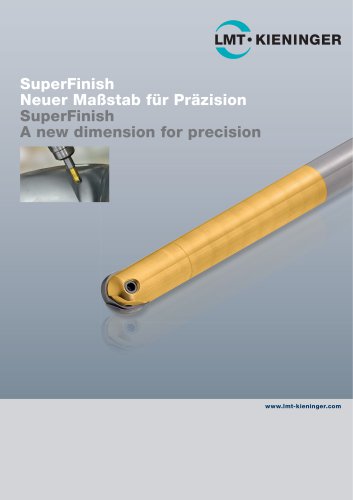 SuperFinish Brochure
4 Pages
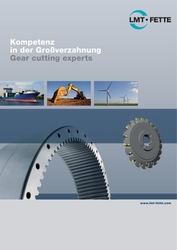 Gear Cutting Experts Brochure
12 Pages
 LMT Belin Milling Catalog
38 Pages
 Indexable Mills Catalog
302 Pages
 End Mills Catalog
154 Pages
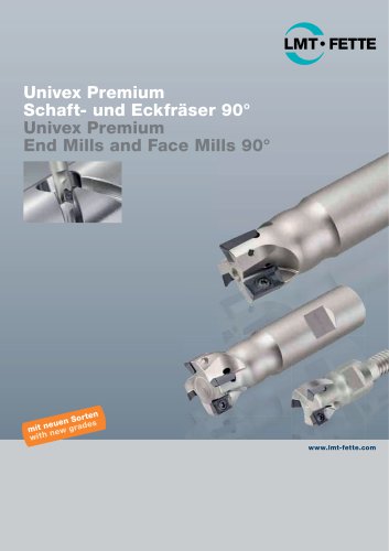 Univex Premium Brochure
20 Pages
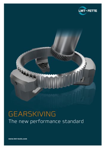 GearSkiving Brochure
6 Pages
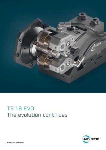 T3.18 EVO Brochure
12 Pages
 HFC – High Feed Cutter Brochure
20 Pages
 EASYMill Brochure
8 Pages
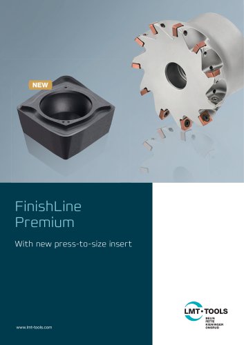 FinishLine Premium Brochure
12 Pages
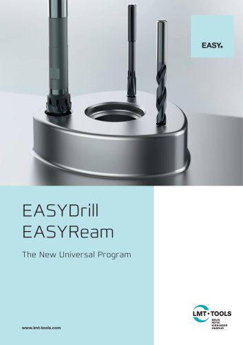 EASYDrill EASYReam Brochure
32 Pages
 EASYTap Brochure
24 Pages
 Automotive Brochure
15 Pages
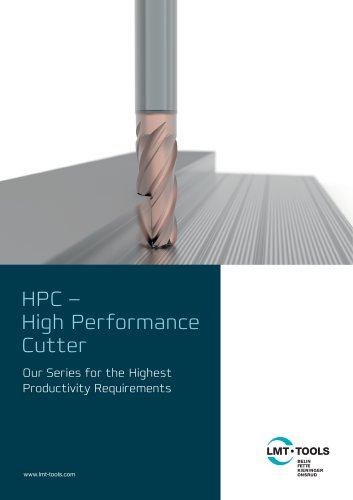
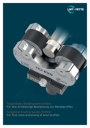
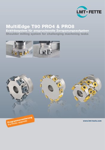

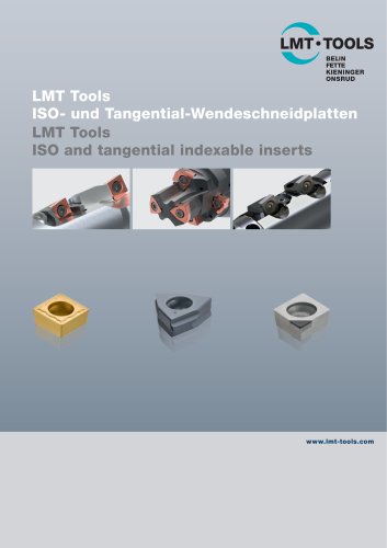
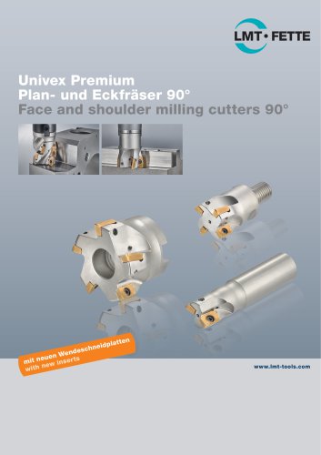
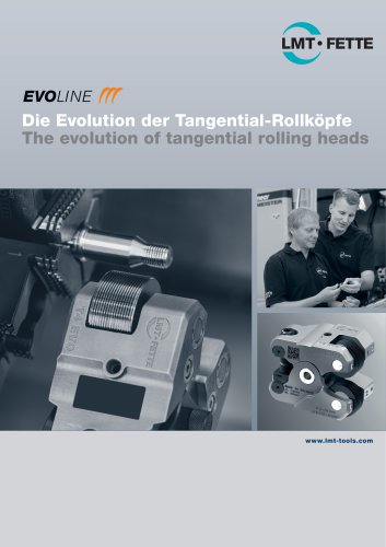
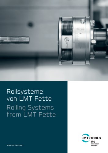
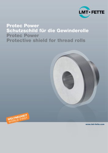
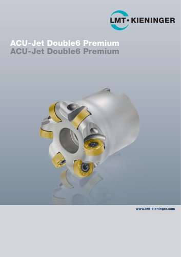

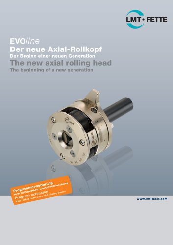

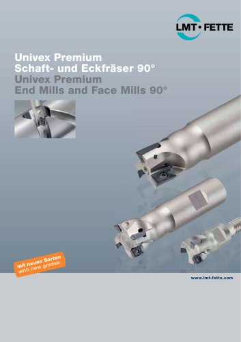
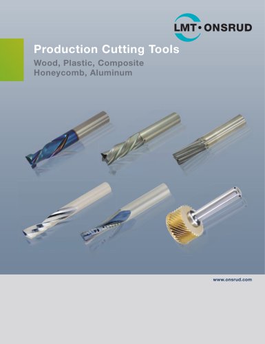
- LMT Tools solid milling cutter
- Drilling tool
- LMT Tools steel milling cutter
- LMT Tools insert milling cutter
- Solid drill bit
- Metal milling cutter
- LMT Tools clamping milling cutter
- LMT Tools milling cutter with cylindrical shank
- End mill
- Cast iron milling cutter
- Face milling cutter
- LMT Tools shell-end milling cutter
- Solid carbide milling cutter
- LMT Tools indexable insert milling cutter
- Ball nose milling cutter
- Multi-purpose drilling tool
- Cutting milling cutter
- Corner radius milling cutter