- Catalogs
- Littelfuse
- Varistors Catalog
- Company
- Products
- Catalogs
- News & Trends
- Exhibitions
Varistors Catalog
1 /254Pages

Varistors Catalog
1 /254Pages
Catalog excerpts

PRODUCT CATALOG & DESIGN GUIDE
Open the catalog to page 1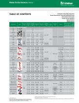
Metal-Oxide Varistors (MOVs) Littelfuse* Expertise Applied | Answers Delivered Introduction to Overvoltage Suppression Varistor Characteristics, Terms and Consideration Factors Varistor Connection Examples Varistor Selection Worksheet Agency Standards Legal Disclaimers Radial Leaded MOVs: LV UltraMOV® Varistor UltraMOV® Varistor UltraMOV® 25S Varistor C-III LA ZA AUMOV® Varistor HMOV Industrial High Energy Terminal MOVs: BA/BB ^ Radial Leaded Screw / Clip Terminals Industrial Packaged Radial Leads Bare Disc Specialty Application MOVs: MA RA High Reliability rZinc • Oxide Axial Leaded Thermally...
Open the catalog to page 2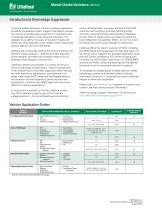
Metal-Oxide Varistors (MOVs) Expertise Applied | Answers Delivered To assure reliable operation, transient voltage suppression should be considered at early stages of the design process. This can be a complex task as electronic components are increasingly sensitive to stray electrical transients. The designer must define the types of transient threats and determine what applications are needed while meeting the product agency norms and standards. Varistors are increasingly used as the front-line solution for transient surge protection. Littelfuse provides expertise to the designer and offers...
Open the catalog to page 3
Expertise Applied | Answers Delivered Introduction to Overvoltage Suppression (continued)Transient Threats - What Are Transients? Voltage transients are defined as short duration surges of electrical energy and are the result of the sudden release of energy that was previously stored, or induced by other means, such as heavy inductive loads or lightning strikes. In electrical or electronic circuits, this energy can be released in a predictable manner via controlled switching actions, or randomly induced into a circuit from external sources. Repeatable transients are frequently caused by the operation...
Open the catalog to page 4
Metal-Oxide Varistors (MOVs) Introduction to Overvoltage Suppression (continued) Transient Voltage Scenarios ESD (Electrostatic Discharge) Electrostatic discharge is characterized by very fast rise times and very high peak voltages and currents. This energy is the result of an imbalance of positive and negative charges between objects. Below are some examples of the voltages which can be generated, depending on the relative humidity (RH): • Walking across a carpet: 35kV @ RH = 20%; 1.5kV @ RH = 65% • Walking across a vinyl floor: 12kV @ RH = 20%; 250V @ RH = 65% • Worker at a bench: kV @ RH =...
Open the catalog to page 5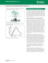
Metal-Oxide Varistors (MOVs) Expertise Applied | Answers Delivered Figure 5. Cloud-to-Ground Lightning Strike Figure 5 shows the effect of a cloud-to-ground strike: the transient-generating effect is far greater. Technological Solutions for Transient Threats Because of the various types of transients and applications, it is important to correctly match the suppression solution to the different applications. Littelfuse offers the broadest range of circuit protection technologies to ensure that you get the proper solution for your application. Please consult our online library of Application Notes...
Open the catalog to page 6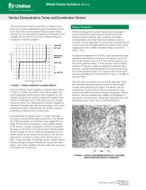
Metal-Oxide Varistors (MOVs) Varistor Characteristics, Terms and Consideration Factors The varistor body structure consists of a matrix of conductive ZNO grains separated by grain boundaries providing P–N junction semiconductor characteristics. These boundaries are responsible for blocking conduction at low voltages and are the source of the nonlinear electrical conduction at higher voltages. Physical Properties VN × d ≈ ----------------3 An attractive property of the MOV is that the PER VERT charelectrical where, d = average grain size FIGURE 1. TYPICAL VARISTOR V-I CHARACTERISTIC The symmetrical,...
Open the catalog to page 7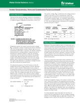
FIGURE 4. CAPACITANCE-VOLTAGE BEHAVIOR OF VARISTOR RESEMBLES A SEMICONDUCTOR ABRUPT-JUNCTION REVERSED BIASED DIODE FIGURE 3. SCHEMATIC DEPICTION OF THE Nd ~ 2 x 10¹⁷/cm3 MICROSTRUCTURE OF A METAL-OXIDE Varistor Characteristics, Terms and Consideration Factors (continued) The bulk of the varistor between contacts is comprised of FIGURE 2. OPTICAL PHOTOMICROGRAPH OF A POLISHED ZnO grains of an ETCHED SECTIONas shown in the schematAND average size "d" OF A VARISTOR ic model of Figure 3. Resistivity of the ZnO is <0.3 Ω–cm. CURRENT varistor at the point on its V-I characteristic where the V transition...
Open the catalog to page 8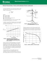
FIGURE 4. CAPACITANCE-VOLTAGE BEHAVIOR OF 2 VARISTOR RESEMBLES A δ SEMICONDUCTOR 0 ABRUPT-JUNCTION REVERSED BIASED DIODE 17ENERGY BAND DIAGRAM OF A 3 Nd ~ 2 x 10 /cm FIGURE 5. 0 0.4 0.8 1.2 ZnO-GRAINBOUNDARY-ZnO JUNCTION Varistor 3. SCHEMATIC DEPICTION OF THE and Consideration Factors (continued) FIGURE Characteristics, Terms 75 150 1.5 INTERGRANULAR In addition, the width ofdv BOUNDARY39 depletion layer was calculated 25VRMS 80 (Note) the 12 1.0 Z X = ------ = V ⁄ α I = R X ⁄ α to be about 1000 Angstrom units. Single junction studies di FIGURE 3.Low voltage formulation. OF THE NOTE: SCHEMATIC...
Open the catalog to page 9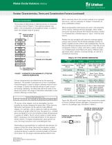
Metal-Oxide Varistors (MOVs) Varistor Characteristics, Terms and Consideration Factors (continued) Varistor Construction The process of fabricating a Littelfuse Varistor is illustrated in the flow chart of Figure 7 The starting material may . differ in the composition of the additive oxides, in order to cover the voltage range of product. ZnO ADDITIVE OXIDES (MAINLY BL203) MIXING POWDER PREPARATION POWDER PRESS SINTER FORM CERAMIC BODY MECHANICAL ASSEMBLY Radials are also available with phenolic coatings applied using a wet process. The PA Series package consists of plastic molded around a 20mm...
Open the catalog to page 10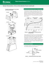
Metal-Oxide Varistors (MOVs) Varistor Characteristics, Terms and Consideration Factors (continued) n = average number of grain boundaries between electrodes LEAKAGE REGION CURRENT (A) NORMAL VARISTOR OPERATION Equivalent Circuit Model An FIGURE 10.model for the varistor CURVE PLOTTED ON by electrical TYPICAL VARISTOR V-I can be represented L LOG-LOG SCALE the simplified equivalent circuit of Figure 11. C FIGURE 12. EQUIVALENT CIRCUIT AT LOW CURRENTS VR FIGURE 4. CAPACITANCE-VOLTAGE BEHAVIOR OF VARISTOR RESEMBLES A SEMICONDUCTOR ABRUPT-JUNCTION REVERSED BIASED DIODE Nd ~ 2 x 10¹⁷/cm3 EV 0 B UPTURN...
Open the catalog to page 11All Littelfuse catalogs and technical brochures
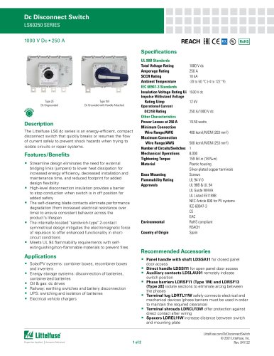 Dc Disconnect Switches
2 Pages
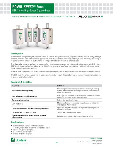 ESR_Fuse_Datasheet
9 Pages
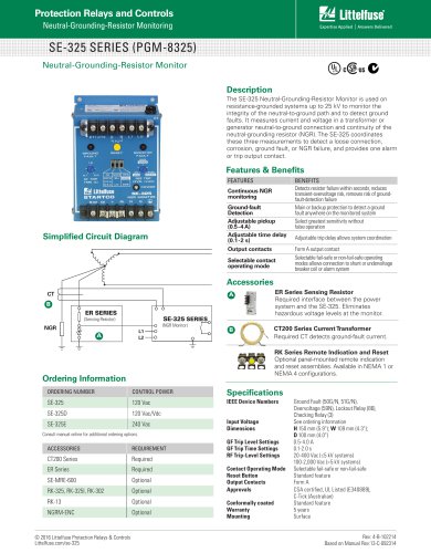 SE-325 SERIES (PGM-8325)
1 Page
 SE-CS10 SERIES
2 Pages
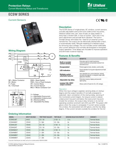 ECSW SERIES
3 Pages
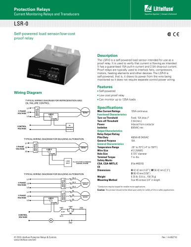 LSR-0
LSR-01 Page
 LSRU SERIES
2 Pages
 LSRX / LSRX-C SERIES
2 Pages
 50R-400-ALT
1 Page
 ALT SERIES
2 Pages
 QJxx30LH4 series
6 Pages
 Thyristors QJ8012xHx Series
8 Pages
 30KPA-HRA Series
7 Pages
 AK1-Y Series
4 Pages
 QJxx40xx Series
8 Pages
 TS Series
11 Pages
 Littelfuse SIDACtor Products Catalog
239 Pages
 Electronic Fuse Products Catalog
409 Pages
 Passenger Car Catalog
60 Pages
 Polyfuse PPTC Catalog
128 Pages
 POWRGARD Electrical Product Catalog
202 Pages
 Protection Relays SSAC Catalog
524 Pages
 Sensors Products Catalog
20 Pages
 SIDACtor Catalog
239 Pages
 TVS Diode Array (SPA) Catalog
215 Pages
 SOLAR PRODUCTS CATALOG
28 Pages
 MP8000
2 Pages
 MicroPlex® SSR18 AND SSR30
2 Pages
 606 Series
3 Pages
 ST Series
3 Pages
 885 Series Fuse
3 Pages
 MicroPlex® 7X, 7H, & 7L
2 Pages
 TPSMB Series
6 Pages
 TPSMD Series
6 Pages
 ISOBUS SYSTEM
2 Pages
 POLYFUSE®
6 Pages
 Passenger Car Solutions
60 Pages
 TVS Diode Catalog
174 Pages
 Switching Thyristor Product Catalog
442 Pages


Archived catalogs
 HIGH-SPEED SEMICONDUCTOR
72 Pages
 INDUSTRIAL CIRCUIT PROTECTION
292 Pages
 Fuse Fundamentals
20 Pages
 Power Semiconductor & IC
133 Pages
 SURGE PROTECTIVE DEVICES
32 Pages
 ELECTRICAL COILS
2 Pages
 PRODUCTS FOR AGRICULTURE
36 Pages
 CIRCUIT PROTECTION
15 Pages
 MSL Classification
2 Pages
 AFTERMARKET PRODUCTS CATALOG
136 Pages
 AFTERMARKET PRODUCTS CATALOG 2018
132 Pages
 Littelfuse Thyristor Catalog
467 Pages


- Temperature probe
- Transformer
- Dry transformer
- Surge protector
- Resistance temperature sensor
- Proximity switch
- Level probe
- Liquid level sensor
- Switching relay
- DIN rail lightning arrester
- Circuit breaker
- Cylindrical proximity sensor
- Class II surge protector
- Panel panel meter
- Isolator switch
- Current transformer
- Protection relay
- Position transducer
- Analog level sensor
- Encapsulated transformer