- Catalogs
- Littelfuse
- TPSMB Series
- Company
- Products
- Catalogs
- News & Trends
- Exhibitions
TPSMB Series
1 /6Pages

TPSMB Series
1 /6Pages
Catalog excerpts

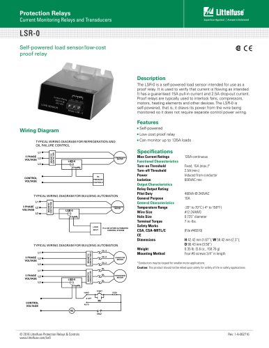
Llttelfuse* Expertise Applied | Answers Delivered TVS DiodesSurface Mount - 600W > TPSMB seriesTPSMB Series I ^ automotive grade HE [RqhS TO @ © The TPSMB series is designed specifically to protect sensitive electronic equipment from voltage transients induced by lightning and other transient voltage events. Agency Approvals Maximum Ratings and Thermal Characteristics (TA=25OC unless otherwise noted) Notes: 1. Non-repetitive current pulse, per Fig.4 and derated above TA=250C per Fig. 3. 2. Mounted on copper pad area of 0.2x0.2" (5.0 x 5.0mm) to each terminal. 3. Measured on 8.3ms single half sine wave or equivalent square wave for unidirectional component only,duty cycle=4 per minute maximum. 4. VF < 3.5V for part number below 300A, VF < 5.0V for part number with 300A or above. DescriptionFeatures • High reliability application and automotive grade AEC Q101 qualified • Surface mount component to optimize board space • Low profile package • Typical failure mode is short from over-specified voltage or current • Whisker test is conducted based on JEDEC JESD201A per its table 4a and 4c • ESD protection of data lines in accordance with IEC 61000-4-2 30kV(Air), 30kV (Contact) • EFT protection of data lines in accordance with IEC 61000-4-4 • Glass passivated chip junction • 600W PPPM (peak pulse power) capability at 10/1000ps waveform, repetition rate (duty cycles):0.01% • Fast response time: typically less than 1.0ns from 0V to VBR min • Excellent clamping capability • Low incremental surge resistance • Typical IR < 1pA for Vr>10.2V • UL Recognized compound meeting flammability rating V-0 • Meet MSL level1, per J-STD-020, High temperature soldering guaranteed: 260°C/10 seconds at terminals • Matte tin lead-free plated • Halogen free and RoHS compliant • Pb-free E3 means 2nd level interconnect is Pb-free and the terminal finish material is tin(Sn) (IPC/ JEDEC J-STD-609A.01) Applications Functional Diagram TVS components are ideal for the protection of I/O Interfaces, VCC bus and other vulnerable circuits used in Automotive applications. © 2018 Littelfuse, Inc. Specifications are subject to change without notice
Open the catalog to page 1
Llttelfuse* Expertise Applied | Answers Delivered TVS DiodesSurface Mount - 600W > TPSMB series Electrical Characteristics (Ta=25°C unless otherwise noted) Note: 1. For bidirectional type having VR of 10 volts and less, the IR limit is double. 2. Vbr @Tj= Vbr@25°C x (1+aT x (Tj - 25)) (aT Temperature Coefficient). 3: The CTI (Comparative Tracking Index) of TPSMB600CA-A and TPSMB650CA-A is 600 and other parts is 550 © 2018 Littelfuse, Inc. Specifications are subject to change without notice. Revised: 09/05/18
Open the catalog to page 2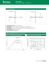
Surface Mount – 600W > TPSMB series Peak Pulse Power Dissipation -- Max power dissipation Stand-off Voltage -- Maximum voltage that can be applied to the TVS without operation Breakdown Voltage -- Maximum voltage that flows though the TVS at a specified test current (IT) Clamping Voltage -- Peak voltage measured across the TVS at a specified Ippm (peak impulse current) Reverse Leakage Current -- Current measured at VR Forward Voltage Drop for Uni-directional Ratings and Characteristic Curves (T =25°C unless otherwise noted) Voltage Transients PPPM-Peak Pulse Power (KW) Figure 2 - Across TVS Voltage...
Open the catalog to page 3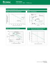
Surface Mount – 600W > TPSMB series Ratings and Characteristic Curves (T =25°C unless otherwise noted) (Continued) A Figure 3 - Peak Pulse Power Derating Curve Figure 4 - Pulse Waveform 150 IPPM- Peak Pulse Current, % IRSM Peak Pulse Power (PPP) or Current (IPP) Derating in Percentage % Half Value IPPM IPPM TJ-Initial Junction Temperature (ºC) IFSM - Peak Forward Surge Current (A) Figure 6 - Maximum Non-Repetitive Peak Forward Surge Current Uni-Directional Only Figure 5 - Typical Junction Capacitance Peak Value IPPM TJ=25°C Pulse Width(td) is defined as the point where the peak current decays...
Open the catalog to page 4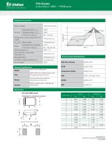
Llttelfuse* Expertise Applied | Answers Delivered TVS DiodesSurface Mount - 600W > TPSMB series Soldering Parameters Dimension in inches and (millimeters) © 2018 Littelfuse, Inc. Specifications are subject to change without notice. Revised: 09/05/18
Open the catalog to page 5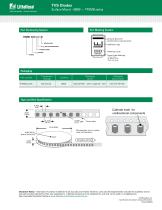
Llttelfuse* Expertise Applied | Answers Delivered TVS DiodesSurface Mount - 600W > TPSMB series Part Marking System Part Numbering System TPSMB XXX C A [-A] DESIGN CODE I 5% VBR VOLTAGE TOLERANCE BI-DIRECTIONAL VBR VOLTAGE ±±J XXXX YMXXX Cathode Band for unidirectional components Littelfuse Logo Marking Code Trace Code Marking Y:Year Code M: Month Code XXX: Lot Code Packaging Part number Tape and Reel Specification 0.157. (4.0) Cathode mark for unidirectional components 0.315 (8.0) © 2018 Littelfuse, Inc. Specifications are subject to change without notice. Revised: 09/05/18 Disclaimer Notice...
Open the catalog to page 6All Littelfuse catalogs and technical brochures
 Dc Disconnect Switches
2 Pages
 ESR_Fuse_Datasheet
9 Pages
 SE-325 SERIES (PGM-8325)
1 Page
 SE-CS10 SERIES
2 Pages
 ECSW SERIES
3 Pages
 LSR-0
LSR-01 Page
 LSRU SERIES
2 Pages
 LSRX / LSRX-C SERIES
2 Pages
 50R-400-ALT
1 Page
 ALT SERIES
2 Pages
 QJxx30LH4 series
6 Pages
 Thyristors QJ8012xHx Series
8 Pages
 30KPA-HRA Series
7 Pages
 AK1-Y Series
4 Pages
 QJxx40xx Series
8 Pages
 TS Series
11 Pages
 Littelfuse SIDACtor Products Catalog
239 Pages
 Electronic Fuse Products Catalog
409 Pages
 Passenger Car Catalog
60 Pages
 Polyfuse PPTC Catalog
128 Pages
 POWRGARD Electrical Product Catalog
202 Pages
 Protection Relays SSAC Catalog
524 Pages
 Sensors Products Catalog
20 Pages
 SIDACtor Catalog
239 Pages
 TVS Diode Array (SPA) Catalog
215 Pages
 Varistors Catalog
254 Pages
 SOLAR PRODUCTS CATALOG
28 Pages
 MP8000
2 Pages
 MicroPlex® SSR18 AND SSR30
2 Pages
 606 Series
3 Pages
 ST Series
3 Pages
 885 Series Fuse
3 Pages
 MicroPlex® 7X, 7H, & 7L
2 Pages
 TPSMD Series
6 Pages
 ISOBUS SYSTEM
2 Pages
 POLYFUSE®
6 Pages
 Passenger Car Solutions
60 Pages
 TVS Diode Catalog
174 Pages
 Switching Thyristor Product Catalog
442 Pages


Archived catalogs
 HIGH-SPEED SEMICONDUCTOR
72 Pages
 INDUSTRIAL CIRCUIT PROTECTION
292 Pages
 Fuse Fundamentals
20 Pages
 Power Semiconductor & IC
133 Pages
 SURGE PROTECTIVE DEVICES
32 Pages
 ELECTRICAL COILS
2 Pages
 PRODUCTS FOR AGRICULTURE
36 Pages
 CIRCUIT PROTECTION
15 Pages
 MSL Classification
2 Pages
 AFTERMARKET PRODUCTS CATALOG
136 Pages
 AFTERMARKET PRODUCTS CATALOG 2018
132 Pages
 Littelfuse Thyristor Catalog
467 Pages


- Temperature probe
- Transformer
- Dry transformer
- Surge protector
- Resistance temperature sensor
- Proximity switch
- Level probe
- Liquid level sensor
- DIN rail lightning arrester
- Switching relay
- Circuit breaker
- Class II surge protector
- Cylindrical proximity sensor
- Panel panel meter
- Protection relay
- Current transformer
- Position transducer
- Isolator switch
- Analog level sensor
- Encapsulated transformer