- Catalogs
- Littelfuse
- SIDACtor Catalog
- Company
- Products
- Catalogs
- News & Trends
- Exhibitions
SIDACtor Catalog
1 /239Pages

SIDACtor Catalog
1 /239Pages
Catalog excerpts

^ U Protection Thyristor Semiconductor Products
Open the catalog to page 1
SIDACtor® Protection Thyristors Littelfuse* Expertise Applied | Answers Delivered SIDACtor Product Description SIDACtor Family Application Selector Table Product Packages Construction and Operation Electrical Parameters Selection Criteria Overvoltage Protection Comparison Custom Part Number Capabilities Quality and Reliability Assurance Global Commitment to Green and Environmental Compliance Telecommunications Protection PCB Layout Considerations for an Ethernet Application or Other High Speed Circuits PCB Placement Guidelines for QFN (Quad Flatpak No-Lead Package) Lead-Free Soldering Recommendations...
Open the catalog to page 2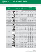
Expertise Applied | Answers Delivered SIDACtor® Protection Thyristors Standoff Series Name Package Type Type (working) Voltage (Vdrm) © 2017 Littelfuse, Inc. Specifications, desSripcions a od illustrative material in this literatnre cre as accurate as known at the time of publication, but are subjectto change without notice. Visit www.littelfuse.com for more information.
Open the catalog to page 3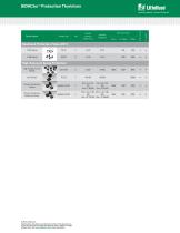
RoHS Compliant SIDACtor ® Protection Thyristors Series Name Package Type Standoff (working) Voltage (VDRM) Peak Pulse Rating: 2x10µs High Exposure Surge Protection: High Surge Current Series Primary Protection Series Primary Protection Balanced Series © 2017 Littelfuse, Inc. Littelfuse, Specifications are subject toand illustrative material in this literature are Specifications, descriptions change without notice. as accurate as known at the time of publication, but are subject to change Revised: 02/23/17 without notice. Visit www.littelfuse.com for more information.
Open the catalog to page 4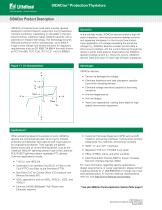
SIDACtor ® Protection Thyristors SIDACtor Product Description SIDACtor components are solid state crowbar devices designed to protect telecom equipment during hazardous transient conditions. Capitalizing on the latest in thyristor advancements, Littelfuse makes SIDACtor devices with a patented ion implant technology. This technology ensures effective protection within nanoseconds, up to 5000 A surge current ratings, and simple solutions for regulatory requirements such as GR 1089, TIA-968-A (formerly known as FCC Part 68), ITU-T K.20, ITU-T K.21, and UL 60950-1. Operation In the standby mode,...
Open the catalog to page 5
SIDACtor® Protection Thyristors Littelfuse* Expertise Applied | Answers Delivered SIDACtor Product Description (continued)Broadband Optimized™ Protection The Broadband Optimized™ family of products is focused on addressing the performance and regulatory requirements of broadband equipment. The Broadband Optimized family, with its wide range of solutions provides applications with the options needed to address the unique protection needs of DSL equipment (up to VDSL) as well as Ethernet (up to 1000baseT). Optimization is accomplished using proprietary and patented approaches that minimize the...
Open the catalog to page 6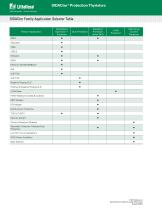
SIDACtor® Protection Thyristors Expertise Applied | Answers Delivered © 2017 Littelfuse, Inc. Specifications are subject to change wit
Open the catalog to page 7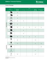
Expertise Applied | Answers Delivered Product Packages © 2017 Littelfuse, Inc. Specifications are subject to change without
Open the catalog to page 8
SIDACtor ® Protection Thyristors Construction and Operation SIDACtor devices are thyristor devices used to protect sensitive circuits from electrical disturbances caused by lightning-induced surges, inductive-coupled spikes, and AC power fault conditions. The unique structure and characteristics of the thyristor are used to create an overvoltage protection device with precise and repeatable turn-on characteristics with low voltage overshoot and high surge current capabilities. Physics The device is a semiconductor device characterized as having four layers of alternating conductivity: PNPN (Figure...
Open the catalog to page 9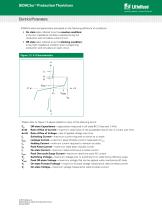
Expertise Applied | Answers Delivered Electrical Parameters SIDACtor electrical parameters are based on the following definition of conditions • On state (also referred to as the crowbar condition) is the low impedance condition reached during full conduction and simulates a short circuit. • Off state (also referred to as the blocking condition) is the high impedance condition prior to beginning conduction and simulates an open circuit. Please refer to Figure 1.3 above related to many of the following terms: Co di/dt dv/dt IS IDRM IH IPP IT ITSM VS V DRM VF VT Off-state Capacitance—capacitance...
Open the catalog to page 10
Llttelfuse* Expertise Applied | Answers Delivered When selecting a SIDACtor® device, use the following criteria: The VDRM of the SIDACtor® device must be greater than the maximum operating voltage of the circuit that the SIDACtor® device is protecting. Example 1: For a POTS (Plain Old Telephone Service) application, convert the maximum operating Ring voltage (150 VRMS) to a peak voltage, and add the maximum DC bias of the central office battery: For longitudinal surges (Tip-Ground, Ring-Ground), RTOTAL is calculated for both Tip and Ring: RSOURCE _ VPK/IPK R = R + R TOTAL RING SOURCE For metallic...
Open the catalog to page 11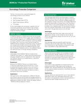
Expertise Applied | Answers Delivered Overvoltage Protection Comparison The four most commonly used technologies for overvoltage protection are as follows: • SIDACtoi® devices • Gas Discharge Tubes (GDTs) • Metal Oxide Varistors (MOVs) • TVS diodes All four technologies are connected in parallel with the circuit being protected, and all exhibit a high off-state impedance when biased with a voltage less than their respective blocking voltages. A SIDACtoi® device is a PNPN device that can be thought of as a thyristor device without a gate. Upon exceeding its peak off-state voltage (VDRM), a SIDACtoi®...
Open the catalog to page 12
SIDACtor ® Protection Thyristors Overvoltage Protection Comparison (continued) TVS Diodes Transient Voltage Suppressor (TVS) diodes are clamping voltage suppressors that are constructed with back-toback PN junctions. During conduction, TVS diodes create a low impedance path by varying their resistance as voltage is applied across their terminals. Once the voltage is removed, the diode will turn off and return to its high offstate impedance. Advantages Because TVS diodes are solid state devices, they do not fatigue nor do their electrical parameters change as long as they are operated within their...
Open the catalog to page 13All Littelfuse catalogs and technical brochures
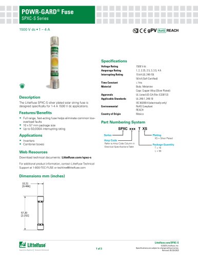
 Dc Disconnect Switches
2 Pages
 ESR_Fuse_Datasheet
9 Pages
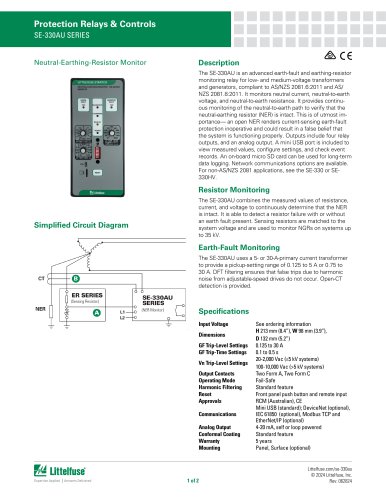
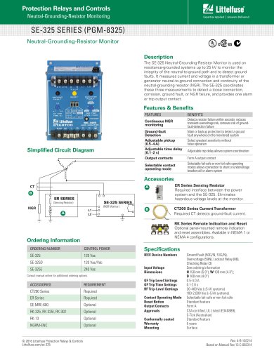 SE-325 SERIES (PGM-8325)
1 Page
 SE-CS10 SERIES
2 Pages
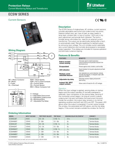 ECSW SERIES
3 Pages
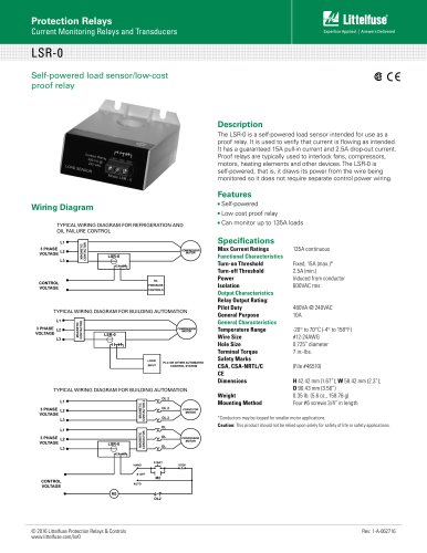 LSR-0
LSR-01 Page
 LSRU SERIES
2 Pages
 LSRX / LSRX-C SERIES
2 Pages
 50R-400-ALT
1 Page
 ALT SERIES
2 Pages
 QJxx30LH4 series
6 Pages
 Thyristors QJ8012xHx Series
8 Pages
 30KPA-HRA Series
7 Pages
 AK1-Y Series
4 Pages
 QJxx40xx Series
8 Pages
 TS Series
11 Pages
 Littelfuse SIDACtor Products Catalog
239 Pages
 Electronic Fuse Products Catalog
409 Pages
 Passenger Car Catalog
60 Pages
 Polyfuse PPTC Catalog
128 Pages
 POWRGARD Electrical Product Catalog
202 Pages
 Protection Relays SSAC Catalog
524 Pages
 Sensors Products Catalog
20 Pages
 TVS Diode Array (SPA) Catalog
215 Pages
 Varistors Catalog
254 Pages
 SOLAR PRODUCTS CATALOG
28 Pages
 MP8000
2 Pages
 MicroPlex® SSR18 AND SSR30
2 Pages
 606 Series
3 Pages
 ST Series
3 Pages
 885 Series Fuse
3 Pages
 MicroPlex® 7X, 7H, & 7L
2 Pages
 TPSMB Series
6 Pages
 TPSMD Series
6 Pages
 ISOBUS SYSTEM
2 Pages
 POLYFUSE®
6 Pages
 Passenger Car Solutions
60 Pages
 TVS Diode Catalog
174 Pages
 Switching Thyristor Product Catalog
442 Pages


Archived catalogs
 HIGH-SPEED SEMICONDUCTOR
72 Pages
 INDUSTRIAL CIRCUIT PROTECTION
292 Pages
 Fuse Fundamentals
20 Pages
 Power Semiconductor & IC
133 Pages
 SURGE PROTECTIVE DEVICES
32 Pages
 ELECTRICAL COILS
2 Pages
 PRODUCTS FOR AGRICULTURE
36 Pages
 CIRCUIT PROTECTION
15 Pages
 MSL Classification
2 Pages
 AFTERMARKET PRODUCTS CATALOG
136 Pages
 AFTERMARKET PRODUCTS CATALOG 2018
132 Pages
 Littelfuse Thyristor Catalog
467 Pages


- Temperature probe
- Transformer
- Dry transformer
- Surge protector
- Resistance temperature sensor
- Proximity switch
- Level probe
- Liquid level sensor
- DIN rail lightning arrester
- Switching relay
- Circuit breaker
- Class II surge protector
- Cylindrical proximity sensor
- Panel panel meter
- Protection relay
- Current transformer
- Position transducer
- Isolator switch
- Analog level sensor
- Encapsulated transformer