 Website:
Littelfuse
Group: Littelfuse
Catalog excerpts

Uttelfuse* Expertise Applied | Answers Delivered
Open the catalog to page 1
POWR-SPEED® Fuses
Open the catalog to page 2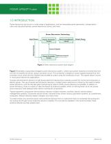
POWR-SPEED® Fuses 1.0 INTRODUCTION Power electronics are found in a wide range of applications, such as renewable power generation, transportation, utility and industrial facilities, power electronics control, and more. Power Electronics Technology Power Converter Circuit Power Conditioner Circuit Output Power Input Power Reference Inputs Power Controller Circuit Figure 1. Power electronics system block diagram Figure 1 illustrates a typical block diagram power electronics system, where input power received is transformed from one form to another (ac-dc-ac) using a converter circuit. This...
Open the catalog to page 3
POWR-SPEED® Fuses 2.0 POWER SEMICONDUCTOR DEVICES The ability to switch (turn on/off) in an inductive circuit with minimum power loss is the key feature of power semiconductor devices. Significant contributions were made by many researchers during the 1960s and 1970s which resulted in the introduction of many common power semiconductor devices that we still use today. The key driving factors for the development of power semiconductor devices are their low material consumption, low cost and their high efficiency. Power semiconductor devices are a combination of power semiconductor components...
Open the catalog to page 4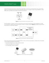
POWR-SPEED® Fuses Three-terminal devices are those whose state is dependent on not only its external power circuit, but also the signal on its driving terminal (this terminal is generally referred to as the gate or base). Power MOSFETs, JFETs, IGBTs, BJTs, and SCRs are examples of three-terminal devices. Emitter Base Figure 3. Three-terminal power semiconductor device With the addition of isolation circuitry to these power semiconductor devices and when packaged as a single unit, the device is called a power semiconductor module or a power module. Figure 4 illustrates a typical power...
Open the catalog to page 5
POWR-SPEED® Fuses 3.0 OVERCURRENT PROTECTION FUNDAMENTALS Understanding the protection requirements and selecting the right fuse for your application can be an overwhelming, time-consuming process even for a seasoned power electronics design engineer. An important part of developing quality overcurrent protection is understanding system needs and overcurrent protective device fundamentals. In this section, the fundamentals of overcurrent protection, construction, and operating characteristics of high-speed fuses are discussed. 3.1 Overcurrent Condition An overcurrent is any current larger...
Open the catalog to page 6
POWR-SPEED® Fuses Figure 6. Power semiconductor device dissipate the heat and help them run cool. Performance of power semiconductor devices, Figure 6, are also greatly affected by the various stresses they handle during their operation such as electrical, mechanical, thermal, and environmental. When these stress levels exceed their withstanding limits, the devices tend to fail. Thermal stress caused by various application conditions is identified as the major factor for semiconductor failure and can result in catastrophic conditions such as case rupture, fire, and explosion which can...
Open the catalog to page 7
POWR-SPEED® Fuses 3.5 High-Speed Fuse Construction The design and construction of high-speed fuses are unique as is their size and terminations. This is done to avoid misapplication of these fuses to any other general industrial applications in the field. Superior grade materials are used for high-speed fuse construction and are described below. Element: High-speed fuses contain one or more current sensitive elements. Each element has a reduced cross section at one or more points. The reduced cross sections provide a measured resistance in each element. The resistance of each element and...
Open the catalog to page 8
POWR-SPEED® Fuses Square Body: These high-speed fuses (Figures 10a and 10b) are made with a premium grade ceramic body, silver-plated copper alloy terminals, high grade quartz silica filler, and an operating mechanism containing 99.9 % pure silver elements. These fuses are available in different sizes to meet the wide range of electrical requirements demanded by modern power semiconductor devices. Silver-Plated Copper Alloy End Bell Aluminum High-Grade Stone Ceramic Body Sand Copper Alloy Endplates ▲ 100% Pure Silver Element Bridges Figure 10b. Square body style fuses The ceramic body has...
Open the catalog to page 9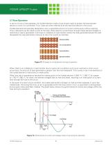
POWR-SPEED® Fuses 3.7 Fuse Operation In terms of how a fuse operates, the fusible element inside a fuse simply melts to protect the downstream device to which it is connected. Thus, fuses are often referred to as the sacrificial device in the circuit. Fusible elements are specially designed to carry a specified amount of current continuously without opening. This is referred to as the rated current of the fuse. When electric current flows through these element bridges or restrictions, heat is generated. Until there is a balance in heat transfer (where the heat generated equals the heat...
Open the catalog to page 10
POWR-SPEED® Fuses Thermal energy generated during the interruption of fault current by the fuse is usually expressed in Joules and commonly referred to as amperes squared seconds (A 2s or l2t). It is proportional to the square of the current (‘l’ in amperes) during the operating time (‘t’ in seconds). The thermal energy generated is represented as melting l2t, arcing l2t, and clearing l2t. Melting l2t: This is the heat energy passed by a fuse after an overcurrent occurs and until the fuse element melts. It equals the rms current squared multiplied by the melting time (in seconds). Arcing...
Open the catalog to page 11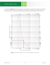
POWR-SPEED® Fuses In the example in Figure 14, the symmetrical (fault) current available for this application is 1800 A which is identified in the X-axis as point A. Follow the line extending from point A up until it meets the TCC at point B. Then moving left to the Y-axis (at point C) determines the pre-arching (melting) time for the fuse selected = 0.002 seconds. Page 13: Figure 14: High-Speed Applications Guide Figure 14. Time current characteristic curve – pre-arcing (melting) time determination
Open the catalog to page 12All Littelfuse catalogs and technical brochures
-
Fuse Fundamentals
20 Pages
-
INDUSTRIAL CIRCUIT PROTECTION
292 Pages
-
SURGE PROTECTIVE DEVICES
32 Pages
-
HIGH-SPEED SEMICONDUCTOR
72 Pages
-
Power Semiconductor & IC
133 Pages
-
Dc Disconnect Switches
2 Pages
-
ESR_Fuse_Datasheet
6 Pages
-
ELECTRICAL COILS
2 Pages
-
PRODUCTS FOR AGRICULTURE
36 Pages
-
CIRCUIT PROTECTION
15 Pages
-
MSL Classification
2 Pages
-
SE-325 SERIES (PGM-8325)
1 Pages
-
SE-CS10 SERIES
2 Pages
-
ECSW SERIES
3 Pages
-
LSR-0
1 Pages
-
LSRU SERIES
2 Pages
-
LSRX / LSRX-C SERIES
2 Pages
-
50R-400-ALT
1 Pages
-
ALT SERIES
2 Pages
-
05903300 & 05903500 RELAYS
1 Pages
-
05930100 & 05930800 RELAYS
1 Pages
-
05931300 & 05931600 RELAYS
1 Pages
-
QJxx30LH4 series
6 Pages
-
Thyristors QJ8012xHx Series
8 Pages
-
30KPA-HRA Series
7 Pages
-
AK1-Y Series
4 Pages
-
QJxx40xx Series
8 Pages
-
TS Series
11 Pages
-
Littelfuse SIDACtor Products Catalog
239 Pages
-
Electronic Fuse Products Catalog
409 Pages
-
Passenger Car Catalog
60 Pages
-
Polyfuse PPTC Catalog
128 Pages
-
POWRGARD Electrical Product Catalog
202 Pages
-
Protection Relays SSAC Catalog
524 Pages
-
Sensors Products Catalog
20 Pages
-
SIDACtor Catalog
239 Pages
-
TVS Diode Array (SPA) Catalog
215 Pages
-
Varistors Catalog
254 Pages
-
SOLAR PRODUCTS CATALOG
28 Pages
-
MP8000
2 Pages
-
MicroPlex® SSR18 AND SSR30
2 Pages
-
606 Series
3 Pages
-
ST Series
3 Pages
-
885 Series Fuse
3 Pages
-
MicroPlex® 7X, 7H, & 7L
2 Pages
-
TPSMB Series
6 Pages
-
TPSMD Series
6 Pages
-
ISOBUS SYSTEM
2 Pages
-
POLYFUSE®
6 Pages
-
Passenger Car Solutions
60 Pages
-
TVS Diode Catalog
174 Pages
-
Switching Thyristor Product Catalog
442 Pages
Archived catalogs
-
AFTERMARKET PRODUCTS CATALOG
136 Pages
-
AFTERMARKET PRODUCTS CATALOG 2018
132 Pages
-
Littelfuse Thyristor Catalog
467 Pages


