
- Catalogs
- Littelfuse
- POWR-GARD Electrical Fuseology & Application Guide


- Company
- Products
- Catalogs
- News & Trends
- Exhibitions
POWR-GARD Electrical Fuseology & Application Guide

POWR-GARD Electrical Fuseology & Application Guide
- Overcurrent Protection: Essential for preventing damage to electrical systems from overcurrents, which can cause overheating, fires, and explosions. Overcurrent protection is mandated by standards such as NEC and OSHA.
- Quality Overcurrent Protection: Must meet legal requirements, ensure safety, minimize damage, provide coordinated protection, be cost-effective, and require minimal maintenance.
- Overcurrent Types: Includes overloads (excessive current in normal paths) and short-circuits (current flowing outside normal paths). Both require timely disconnection to prevent damage.
- Current Rating: Fuses must match the system's normal running current and comply with NEC requirements.
- Voltage Rating: Fuses must operate at or below their rated voltage. Exceeding this can cause fuse destruction.
- Interrupting Rating: Indicates the maximum current a fuse can safely interrupt. Fuses should have ratings that exceed the available fault current.
- Type of Protection: Fuses provide both overload and short-circuit protection, with inverse time characteristics ensuring faster response to higher currents.
- These tools help in understanding the response time of fuses to different levels of overcurrent, aiding in the selection of appropriate fuses for specific applications.
- Ensures that only the protective device closest to the fault opens, minimizing system downtime and maintaining system integrity.
- Different classes of fuses are designed for specific applications, each with unique characteristics and compliance requirements.
- Provides clarity on technical terms used throughout the guide, essential for understanding fuse application and selection.
- Offers guidance on selecting fuses for motor protection, considering factors like starting currents and overload conditions.
- Aids in selecting the appropriate fuse class based on application requirements and system specifications.
- Provides a quick reference for comparing different fuse types and their applications.
The document provides a detailed guide on selecting the correct fuse ampere ratio to maintain selectively coordinated systems. It includes a table (Table 4) that outlines the ratios expressed as Line-Side Fuse to Load-Side Fuse. The Littelfuse product line offers pre-engineered solutions like the LPS Series POWR-Switch and LCP Selective Coordination Panel, which comply with NEC requirements.
National Electrical Code (NEC) Requirements
The document references NEC Article 110, which covers the examination, identification, installation, and use of equipment, emphasizing the importance of interrupting ratings and circuit impedance. Article 240 discusses overcurrent protection, highlighting the need for effective protection to prevent excessive temperatures in conductors.
UL/CSA Fuse Classes and Applications
The document categorizes various fuse classes, including Class L, R, K, J, G, RK1, RK5, K5, T, CC/CD, K1, H, and plug fuses. Each class is described with its standards, voltage ratings, current ratings, interrupting ratings, and specific features like time delay and interchangeability. For instance, Class L fuses have a voltage rating of 600 volts and current ratings from 601-6000 amps, with an interrupting rating of up to 200,000 amps.
Supplementary Overcurrent Protection
Fuses for supplementary overcurrent protection are classified into micro fuses, miniature fuses, and miscellaneous cartridge fuses, each with specific voltage and current ratings. These fuses are designed for special applications and may be UL Recognized for use in UL Listed equipment.
Technical Definitions
The document includes definitions of technical terms such as adjustable alarm level, ampacity, ampere rating, and ampere-squared-seconds (I2t), which describe the thermal energy generated by current flow. It also explains concepts like arc-blast and arc-flash, which are critical for understanding the safety implications of electrical systems.
This section provides definitions of key terms related to electrical systems and fuse applications. Important terms include:
- Open CT Hazard: High voltage risk when CT secondary is open-circuited.
- Overcurrent: Current exceeding equipment's rated capacity.
- Overload: Overcurrent within normal path causing potential damage.
- Peak Let-through Current: Maximum current passing through a protective device during clearing time.
- Power Factor (X/R): Relationship between inductive reactance and resistance during faults.
- Protection Boundaries: Boundaries to protect personnel from electrical hazards.
- Selective Coordination: System where only the immediate protective device opens during a fault.
This section discusses the selection and application of fuses for motor protection:
- Time-Delay Fuses: Designed to withstand temporary overcurrents without opening immediately.
- Motor Protection Tables: Guidelines for selecting fuse ratings based on motor horsepower and full load amperes (FLA).
- Voltage Rating: Maximum voltage at which a fuse is designed to operate.
Guidelines for selecting fuses for motor running protection based on motor horsepower and actual full load currents. The tables provide recommendations for:
- Motor Running Protection: Fuse ratings without overload relays.
- Back-up Motor Running Protection: Fuse ratings with overload relays.
Figures and charts illustrate concepts such as peak let-through current, symmetrical and asymmetrical currents, and threshold current determination. These visual aids help in understanding the behavior of electrical currents and the role of fuses in protection.
- Ensure to check specific mounting dimensions before substituting components.
- Verify fuse characteristics and mounting dimensions for the specific application before substitution.
- For amperages between 1/10 and 30, order non-indicating FLNR series fuses.
- Confirm voltage suitability for DC applications.
- Littelfuse has discontinued Class H fuses and recommends upgrading to RK1 or RK5 Class fuses.
- A fuse can be used in circuits where its voltage rating is equal to or greater than the circuit voltage, unless otherwise specified.
- Example: The FLSR_ID indicating fuse has a voltage rating of 75-600 volts and can be used on circuits with voltages of 600, 480, 250, 125, or 75 volts.
- Never use a fuse in a circuit with a higher rated voltage than the fuse itself.
- For more technical information and application data, visit littelfuse.com.
- Contact the Technical Support Group at 800-TEC-FUSE for inquiries.
- Specifications and descriptions are accurate as of the publication date but are subject to change without notice.
Catalog excerpts

Application Guide POWR-GARD Technical Application Guide
Open the catalog to page 1
This Technical Application Guide or ‘Fuseology’ provides the information needed to select the correct types of Littelfuse POWR-GARD® fuses for most applications. If there are any questions or if additional data is needed for a specific use, call the Littelfuse Technical Support and Engineering Service Group at 1-800-TEC-FUSE (1-800-832-3873), email them at [email protected] or visit us at littelfuse.com. Technical Information White papers, and a library of technical information is available online at littelfuse.com/technicalcenter © 2014 Littelfuse POWR-GARD® Products
Open the catalog to page 2
Technical Application Guide FUSEOLOGY FUNDAMENTALS I. OVERCURRENT PROTECTION FUNDAMENTALS (FUSES AND HOW THEY WORK) Introduction 3. Minimizes overcurrent damage to property, equipment, and electrical systems. 4. Provides coordinated protection. Only the protective device immediately on the line side of an overcurrent opens to protect the system and minimize unnecessary downtime. An important part of developing quality overcurrent protection is an understanding of system needs and overcurrent protective device fundamentals. This section discusses these topics with special attention to the application...
Open the catalog to page 3
Technical Application Guide FUSEOLOGY FUNDAMENTALS temperature of 150°C. Any currents larger than this may immediately vaporize organic insulations. Arcs at the point of fault or from mechanical switching such as automatic transfer switches or circuit breakers may ignite the vapors causing violent explosions and electrical flash. Even though government-mandated high-efficiency motors and NEMA Design E motors have much higher locked rotor currents, POWR-PRO® time-delay fuses such as the FLSR_ ID, LLSRK_ID, or IDSR series have sufficient time-delay to permit motors to start when the fuses are properly...
Open the catalog to page 4
Technical Application Guide SELECTION CONSIDERATIONS Voltage Rating The recommendation to standardize on fuses with at least a 200,000 ampere interrupting rating (AIR) ensures that all fuses have an adequate interrupting rating while providing reserve interrupting capacity for future increases in available fault current. The voltage rating of a fuse is the maximum AC or DC voltage at which the fuse is designed to operate. Fuse voltage ratings must equal or exceed the circuit voltage where the fuses will be installed, and fuses used in DC circuits must be specifically rated for DC applications....
Open the catalog to page 5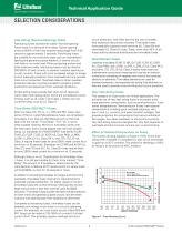
Technical Application Guide SELECTION CONSIDERATIONS circuit protection, and often permits the use of smaller, less expensive disconnect switches. Time-delay fuses have gradually replaced most one-time (UL Class K5) and renewable (UL Class H) fuses. Today, more than 50% of all fuses sold by electrical distributors are time-delay fuses. Fast-Acting (Normal-Opening) Fuses Fast-acting fuses (sometimes called “Normal-opening” fuses) have no intentional time-delay. Typical opening times at 500% of the fuse ampere rating range from 0.05 second to approximately 2 seconds. Fast-Acting fuses are suitable...
Open the catalog to page 6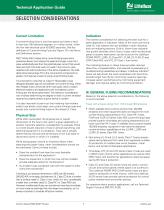
Technical Application Guide SELECTION CONSIDERATIONS Current Limitation Indication The newest consideration for selecting the best fuse for a given application is indication. Many of the more commonly used UL fuse classes are now available in both indicating and non-indicating versions. Built-in, blown-fuse indication that quickly identifies which fuse or fuses within an electrical panel or system have blown can be found on the Littelfuse POWR-PRO® LLSRK_ID Class RK1, FLNR_ID, FLSR_ID and IDSR Class RK5, and JTD_ID Class J fuse series. A current-limiting fuse is one that opens and clears a fault...
Open the catalog to page 7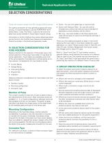
Technical Application Guide SELECTION CONSIDERATIONS Fuses with ampere ratings from 601 through 6,000 amperes • Screw – for use with spade lugs or ring terminals. For superior protection of most general-purpose and motor circuits, it is recommended to use the POWR-PRO® KLPC series Class L fuses. The Class L fuses are the only timedelay fuse series available in these higher ampere ratings. • Screw with Pressure Plate – for use with solid or stranded wire without terminal and recommended for applications where vibration will be a factor. • Box Lug – the most durable of the three options and used...
Open the catalog to page 8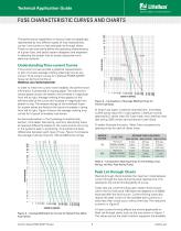
Technical Application Guide The performance capabilities of various fuses are graphically represented by two different types of fuse characteristic curves: time-current curves and peak let-through charts. These curves and charts define the operating characteristics of a given fuse, and assist system designers and engineers in selecting the proper fuse to protect equipment and electrical systems. Understanding Time-current Curves Time-current curves provide a graphical representation or plot of a fuse’s average melting (opening) time at any current. Time-current curves for Littelfuse POWR-GARD®...
Open the catalog to page 9
Technical Application Guide FUSE CHARACTERISTIC CURVES AND CHARTS Peak current which would occur without current limitation The diagonal curves that branch off the A-B line illustrate the current-limiting effects of different fuse ampere ratings for a given fuse series. To continue the example from above, enter the chart in Figure 7 on the bottom at 100,000 rms symmetrical amperes and read upwards to the intersection of the 200 ampere fuse curve. Now read from this point horizontally to the left and read a peak let-through current of approximately 20,000 amperes. Peak Let-Thru Current What this...
Open the catalog to page 10
Technical Application Guide FUSE CHARACTERISTICS CURVES AND CHARTS Only the overcurrent device immediately on the line side of an overcurrent will open for any overload or short-circuit condition. In a selective system, none of this occurs. Overloads and faults are disconnected by the overcurrent protective device immediately on the line side of the problem. The amount of equipment removed from service is minimized, the faulted or overloaded circuit is easier to locate, and a minimum amount of time is required to restore full service. Since the advent of electrical and electronic equipment, businesses...
Open the catalog to page 11All Littelfuse catalogs and technical brochures
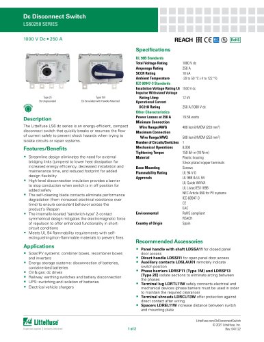 Dc Disconnect Switches
2 Pages
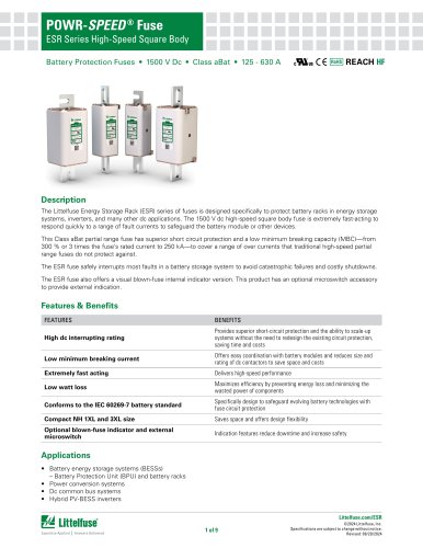 ESR_Fuse_Datasheet
9 Pages
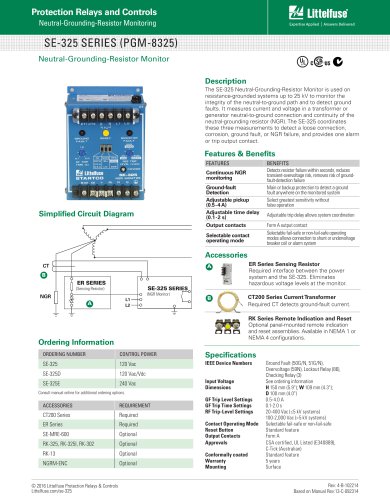 SE-325 SERIES (PGM-8325)
1 Page
 SE-CS10 SERIES
2 Pages
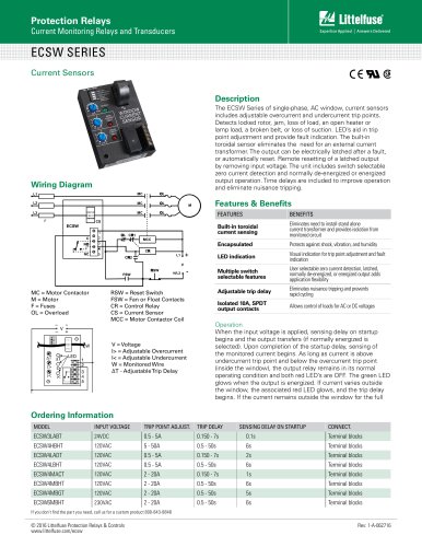 ECSW SERIES
3 Pages
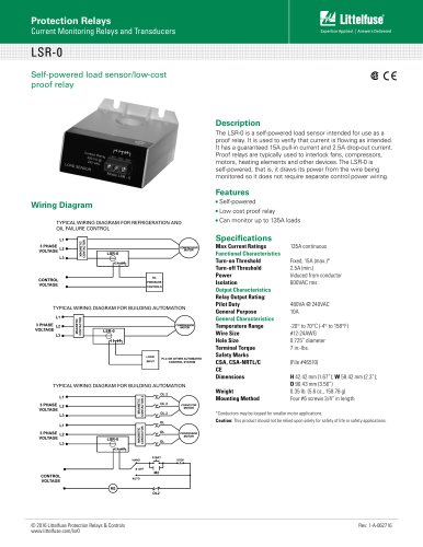 LSR-0
LSR-01 Page
 LSRU SERIES
2 Pages
 LSRX / LSRX-C SERIES
2 Pages
 50R-400-ALT
1 Page
 ALT SERIES
2 Pages
 QJxx30LH4 series
6 Pages
 Thyristors QJ8012xHx Series
8 Pages
 30KPA-HRA Series
7 Pages
 AK1-Y Series
4 Pages
 QJxx40xx Series
8 Pages
 TS Series
11 Pages
 Littelfuse SIDACtor Products Catalog
239 Pages
 Electronic Fuse Products Catalog
409 Pages
 Passenger Car Catalog
60 Pages
 Polyfuse PPTC Catalog
128 Pages
 POWRGARD Electrical Product Catalog
202 Pages
 Protection Relays SSAC Catalog
524 Pages
 Sensors Products Catalog
20 Pages
 SIDACtor Catalog
239 Pages
 TVS Diode Array (SPA) Catalog
215 Pages
 Varistors Catalog
254 Pages
 SOLAR PRODUCTS CATALOG
28 Pages
 MP8000
2 Pages
 MicroPlex® SSR18 AND SSR30
2 Pages
 606 Series
3 Pages
 ST Series
3 Pages
 885 Series Fuse
3 Pages
 MicroPlex® 7X, 7H, & 7L
2 Pages
 TPSMB Series
6 Pages
 TPSMD Series
6 Pages
 ISOBUS SYSTEM
2 Pages
 POLYFUSE®
6 Pages
 Passenger Car Solutions
60 Pages
 TVS Diode Catalog
174 Pages
 Switching Thyristor Product Catalog
442 Pages



Archived catalogs
 HIGH-SPEED SEMICONDUCTOR
72 Pages
 INDUSTRIAL CIRCUIT PROTECTION
292 Pages
 Fuse Fundamentals
20 Pages
 Power Semiconductor & IC
133 Pages
 SURGE PROTECTIVE DEVICES
32 Pages
 ELECTRICAL COILS
2 Pages
 PRODUCTS FOR AGRICULTURE
36 Pages
 CIRCUIT PROTECTION
15 Pages
 MSL Classification
2 Pages
 AFTERMARKET PRODUCTS CATALOG
136 Pages
 AFTERMARKET PRODUCTS CATALOG 2018
132 Pages
 Littelfuse Thyristor Catalog
467 Pages


- Data connector
- Temperature probe
- Transformer
- Dry transformer
- Surge protector
- Resistance temperature sensor
- Proximity switch
- Level probe
- Switching relay
- Liquid level sensor
- Cylindrical proximity sensor
- Class II surge protector
- Panel panel meter
- Protection relay
- Current transformer
- Position transducer
- IP67 proximity sensor