
- Catalogs
- Littelfuse
- LSR-0


- Company
- Products
- Catalogs
- News & Trends
- Exhibitions
LSR-0
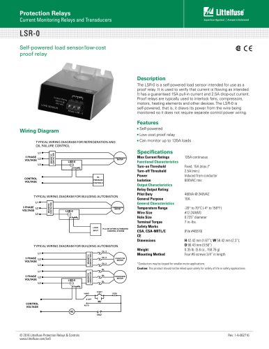
LSR-0
- Max Current Ratings: 135A continuous
- Turn-on Threshold: Fixed at 15A (max.)
- Turn-off Threshold: 2.5A (min.)
- Isolation: 600VAC rms
- Output Characteristics: Pilot Duty 480VA @ 240VAC, General Purpose 10A
- Temperature Range: -20° to 70°C (-4° to 158°F)
- Wire Size: #12-24AWG
- Hole Size: 0.725” diameter
- Terminal Torque: 7 in.-lbs.
- Safety Marks: CSA, CSA-NRTL/C, CE
- Dimensions: H 42.42 mm (1.67”); W 58.42 mm (2.3”); D 90.43 mm (3.56”)
- Weight: 0.35 lb. (5.6 oz., 158.76 g)
- Mounting Method: Four #6 screws 3/4” in length
Catalog excerpts
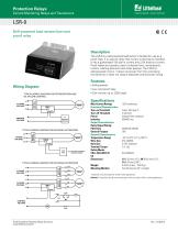
Protection Relays Current Monitoring Relays and Transducers LSR-0 Self-powered load sensor/low-cost proof relay Description The LSR-0 is a self-powered load sensor intended for use as a proof relay. It is used to verify that current is flowing as intended. It has a guaranteed 15A pull-in current and 2.5A drop-out current. Proof relays are typically used to interlock fans, compressors, motors, heating elements and other devices. The LSR-0 is self-powered, that is, it draws its power from the wire being monitored so it does not require separate control power wiring. Features Wiring Diagram TYPICAL WIRING DIAGRAM FOR REFRIGERATION AND OIL FAILURE CONTROL Low cost proof relay TYPICAL WIRING DIAGRAM FOR BUILDING AUTOMATION TYPICAL WIRING DIAGRAM FOR BUILDING AUTOMATION Max Current Ratings Functional Characteristics Turn-on Threshold Turn-off Threshold Power Isolation Output Characteristics Relay Output Rating: Pilot Duty General Purpose General Characteristics Temperature Range Wire Size Hole Size Terminal Torque Safety Marks CSA, CSA-NRTL/C CE Dimensions Weight Mounting Method 135A continuous Fixed, 15A (max.)* 2.5A (min.) Induced from conductor 600VAC rms *Conductors may be looped for smaller motor applications. Caution: This product should not be relied upon solely for safety of life or safety applications. © 2016 Littelfuse Protection Relays & Controls www.littelfuse.com/lsr0
Open the catalog to page 1All Littelfuse catalogs and technical brochures
 Dc Disconnect Switches
2 Pages
 ESR_Fuse_Datasheet
9 Pages
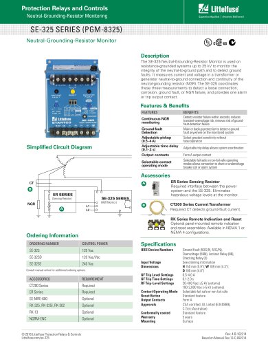 SE-325 SERIES (PGM-8325)
1 Page
 SE-CS10 SERIES
2 Pages
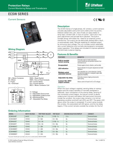 ECSW SERIES
3 Pages
 LSRU SERIES
2 Pages
 LSRX / LSRX-C SERIES
2 Pages
 50R-400-ALT
1 Page
 ALT SERIES
2 Pages
 QJxx30LH4 series
6 Pages
 Thyristors QJ8012xHx Series
8 Pages
 30KPA-HRA Series
7 Pages
 AK1-Y Series
4 Pages
 QJxx40xx Series
8 Pages
 TS Series
11 Pages
 Littelfuse SIDACtor Products Catalog
239 Pages
 Electronic Fuse Products Catalog
409 Pages
 Passenger Car Catalog
60 Pages
 Polyfuse PPTC Catalog
128 Pages
 POWRGARD Electrical Product Catalog
202 Pages
 Protection Relays SSAC Catalog
524 Pages
 Sensors Products Catalog
20 Pages
 SIDACtor Catalog
239 Pages
 TVS Diode Array (SPA) Catalog
215 Pages
 Varistors Catalog
254 Pages
 SOLAR PRODUCTS CATALOG
28 Pages
 MP8000
2 Pages
 MicroPlex® SSR18 AND SSR30
2 Pages
 606 Series
3 Pages
 ST Series
3 Pages
 885 Series Fuse
3 Pages
 MicroPlex® 7X, 7H, & 7L
2 Pages
 TPSMB Series
6 Pages
 TPSMD Series
6 Pages
 ISOBUS SYSTEM
2 Pages
 POLYFUSE®
6 Pages
 Passenger Car Solutions
60 Pages
 TVS Diode Catalog
174 Pages
 Switching Thyristor Product Catalog
442 Pages



Archived catalogs
 HIGH-SPEED SEMICONDUCTOR
72 Pages
 INDUSTRIAL CIRCUIT PROTECTION
292 Pages
 Fuse Fundamentals
20 Pages
 Power Semiconductor & IC
133 Pages
 SURGE PROTECTIVE DEVICES
32 Pages
 ELECTRICAL COILS
2 Pages
 PRODUCTS FOR AGRICULTURE
36 Pages
 CIRCUIT PROTECTION
15 Pages
 MSL Classification
2 Pages
 AFTERMARKET PRODUCTS CATALOG
136 Pages
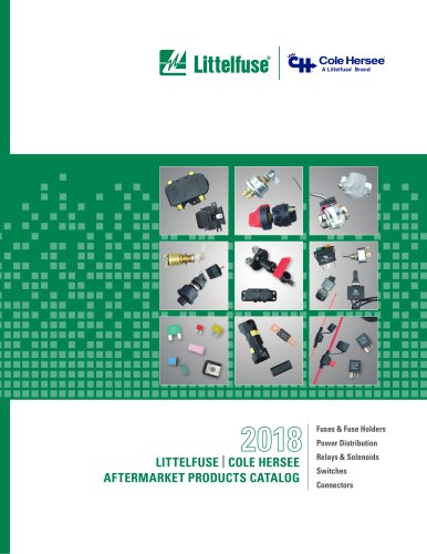 AFTERMARKET PRODUCTS CATALOG 2018
132 Pages
 Littelfuse Thyristor Catalog
467 Pages


- Connector
- Data connector
- Temperature probe
- Transformer
- Dry transformer
- Surge protector
- Resistance temperature sensor
- Proximity switch
- Level probe
- Switching relay
- Liquid level sensor
- Cylindrical proximity sensor
- Circuit breaker
- Class II surge protector
- Panel panel meter
- Isolator switch
- Current transformer
- Position transducer
- IP67 proximity sensor